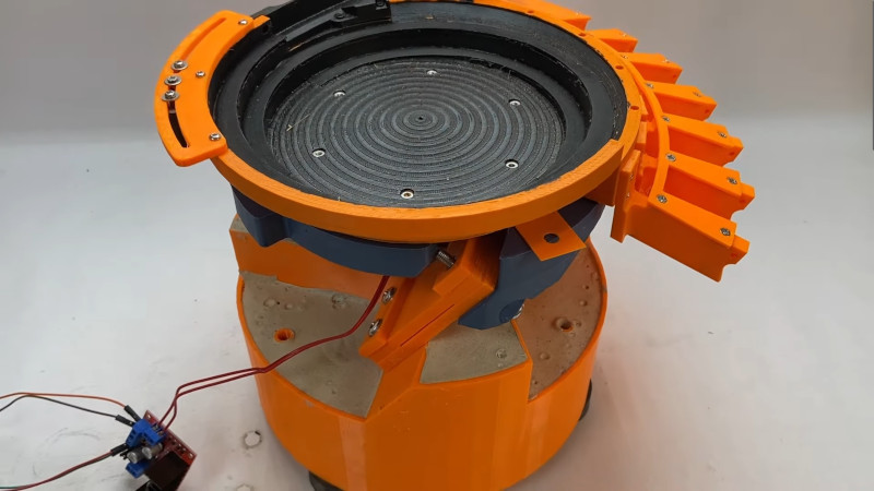
If you spend much time around industrial processes, you may have seen a vibrating bowl feeder at work. It’s a clever but simple machine that takes an unruly pile of screws or nuts and bolts, and delivers them in a line the correct way up. They do this by shaking the pile of fasteners in a specific way — a spiral motion which encourages them to work to the edge of the pile and align themselves on a spiral track which leads to a dispenser. It’s a machine [Fraens] has made from 3D printed parts, and as he explains in the video below the break, there’s more to this than meets the eye.
The basic form of the machine has a weighted base and an upper bowl on three angled springs. Between the two is an electromagnet, which provides the force for the vibration. The electromagnet needed to be driven with a sine wave which he makes with an Arduino and delivers as PWM via an H-bridge, but the meat of this project comes in balancing the force and frequency with the stiffness of the springs. He shows us the enormous pile of test prints made before the final result was achieved, and it’s a testament to the amount of work put into this project. The final sequence of a variety of objects making the march round the spiral is pure theatre, but we can see his evident satisfaction in a job well done.
Oddly this isn’t the first bowl feeder we’ve seen, though it may be one of the most accomplished. We particularly like this tiny example for SMD parts.


as seen on almost half of all the episodes of ‘how its made’
Retired now, but would be interested in the detail of the coil firing circuit.
I used linear vibratory feeders for many years, progressed from purpose designed SCR driving circuits to “off the shelf” components that allowed very fine control over the voltage without to much cpu time.
Basically a small transformer produced a 3 vac signal that was used to detect zero crossing as an input to the cpu. Using a delayed pulse to fire a Zero Cross AC SSR, the on-time could be accurately controlled. I was able to feed and weigh diamonds at 3 per second very reliably. Even small round balls of fertiliser like the video showed which are hard to stop once they get rolling.
Very impressive design of springs, which are the key to achieving a vibration close to resonance.
Does anyone know what printer he is using?
A “3D” printer.
Funny!
That’s gonna be a Voron 2.4 (could be earlier but looks recent), open-source DIY design :)
Thank you.
Voron 2.4
Not 100% sure but i think it’s a Voron
Yes. I do.
ok jokes aside, I think it is this:
https://www.3djake.at/bewertungen/ldo-motors/voron-24-350-bausatz
I have not seen one of these in a long time. The one I saw was back in the early 80’s and it was built by a bunch of folks from IBM and it took flat pack IC’s in their carriers and put them in plastic tubes. The tricks that pulled that this one was missing, and OMG, it came so close… Was it had some traps on the ramp. For example as the ramp went up, at one point, it got skinner. One of the flat packs in the right orientation would be happy and hang on, but one in the wrong orientation would fall back into the bowl and get to try again. There was a second trap for which end was up, and this one depended on one end of the package weighing a bit more than the other, and on the way up the ramp started also going up at an angle facing back down into the bowl, and parts that were not facing the right way fell back in and got to try again. The parts that did not fall back in fell into the plastic carrier tube, all right side up and with pin 1 pointing the right way. There was a opto interrupter at the height of the top of the tube, and that would beep and stop the machine when someone needed to put a new carrier in. It was a pretty cool contraption to watch work. I recall back when I first saw it thinking that someone put a lot of time into it.
I always think of things like this before rapid iteration was a thing. How many hours did the designer spend trying a new ramp profile or wedge thickness? Amazing dedication. We are very lucky nowadays to have parametric designs and rapid prototyping.
To me this looks like those funnel coin things at malls except in reverse.
~$15k to have Automation devices build and tune one to your specific product.
This! This is what’s amazing about this build.
I don’t quite understand what you’re trying to say.
>~$15k to have Automation devices build and tune one to your specific product.
Automation Devices is a company. They manufacture vibratory bowl feeders. We had a client order one for a packaging line in 2013, ran them $15k tuned to their product. (upon checking the invoice that price included several accessories the bowl and base were closer to $10k my bad)
Bowl: 18” Diameter stainless steel bowl / brush finish / center mount / clockwise
Base Unit: Model 15 Base Unit / 120volt, 60hz / 6800.1 Variable Speed Controller
Part Orientation: lying flat.
Feed Rate: deleted
Price, one Feeding System ………………………………………………………………………………..$9,608.00 USD.
If you buy one of these machines off ebay for a couple hundred to a couple of thousand and have good luck, theyll run okay. IF your lucky, and have very loose requirements and an ideal product for the bowl and vibratory head as it they are tuned when you get them.
I get that this is a crabapple to apple comparison. Im in no way implying theirs is as capable or worth as much. But I think its a pretty cool step in the right direction and felt sharing the knowledge of commercial price was worthwhile.
Having worked with the full sized versions of these in the past. Adding a couple of small adjustable fingers to knock items back into the bowl, can help with orientation and avoid jamming due to double stacked items. Not to mention the addition of an optical gate to count the output or even something like a distance sensor above the bowl if it’s being fed by something else, to avoid over filling. Depending on what they are feeding, getting the output consistently running without constant supervision can be somewhat of an art.
We used TONS of vibratory feed bowls for final testing SOT-23 components. They work on the principle of static versus dynamic friction and use something more like a triangle wave drive instead of a sine wave.
I should have said sawtooth wave. When are we going to get a edit capability??
It looks, like people are proud of printed tests or print failures. I consider them the just the opposite. It is a shame to produce a lot of plastic waist.
If I make something, it probably won’t work the first time.
You are ashamed when that happens? You must be very good at what you do!
They are probably meaning excessive waste. If it is a large part then print specific test pieces first to check the fit, rather than doing that with a full part. You can also minimize waste by spending more time designing it and thinking about it before printing.
Reprints can also be minimized by understanding your printer and what it is capable of and having it well calibrated.
People also avoid post processing but it shouldn’t be avoided for one offs or prototypes. If you need a really tight fit then make it deliberately not fit, like making a hole and peg exactly the same size without any tolerances and then sand it or drill the hole until it is a tight fit.
Reprints can also be avoided by smart design decisions like making parts adjustable or clamping rather than just relying on press fits or friction fits.
Your goal for most parts or pretty much anything you do should be to minimize how many times you get it wrong. Spending a little more time when designing or analysing why a part doesn’t work can mean you get it better the next time or get it right in less iterations saving print time and material too. Think about machinists, they don’t produce 5 copies of a full part with slightly different sized holes until they get it right, they spend more time designing and measuring since material and machining time is expensive. Think about injection moulds, people want to get them right first time or with only minor adjustment since they are expensive. Any other manufacturing or design process and you would be expected to have some form of education in it, to minimize failures. 3D printing is that accessible and cheap it has become lazy, people aren’t spending as long designing a part of properly thinking the problem through, they just think because the printer is fast and cheap enough to run that they can just make many different iterations rather than trying to get it right first time. It actually ends up taking longer with all the iterations than it would if it was properly designed from the start and printed on a properly calibrated machine.
I do not get bent over a few 3D printed pieces, they are nothing in the grand scheme, but I was watching a tour of a pcb fab plant and I was a bit struck at how big and structural the tape was that the parts come on. Like the waste packaging is bigger than the component.
I agree with you. You shouldn’t be proud of producing garbage. Unfortunately, building prototypes often results in prints that are no longer needed. I’ve been thinking about this problem for a long time. It could be that there is a market here that could recycle 3D printing material. However, mixing different materials is problematic. The presentation in the video served as a gap filler and to show what was necessary.
Honestly, for the scale/scope here, it wasn’t all that much waste at all. Fine-tuning the springs basically has to be trial-and-error, so there’s no getting around that. But the main body of it looks like it worked on the 2nd try? That’s pretty amazing.
If you add up all the baby Grogu heads gathering dust in drawers across the world, I think this is plastic well spent!
But it’s also nice to see when a project like this is hard. And somehow the mountain of prototype parts embodies that perfectly.
Exactly, failed prints do not equal effort or work put into the project like the article states. What actually takes more effort and work is doing everything you can to try and make sure it works with as few attempts as possible.
Having lots of discarded prints is generally a sign of laziness, rather than spending time to figure out what was wrong with a part you just change a small bit and reprint and then it also doesn’t work. I have also seen discarded parts due to laziness when trying to get the fit right on a part, especially on YouTube videos, just slightly changing the size and reprinting until it is good enough, rather than making it adjustable or having a proper look at it and measuring the size you need. It is easy to see some of these YouTubers don’t pay for their filament.
Instead of discarded, failed prints being a sign of work and effort instead designing it properly should be encouraged. Fully think and model the design before you even think about printing it. Know the tolerances of your machine and analyse the assembled model in CAD to make sure it would work before printing any part. Sure you may still need to reprint some parts if very tight tolerances are needed but that can be avoided by printing test pieces, that are just that specific section and don’t use any more plastic than needed. Also post processing should be used, if a part is ever so slightly off then sand it. If a very tight tolerance is needed make it so that it doesn’t fit but you can sand it to a tight fit. You shouldn’t be reprinting parts if a hole is slightly too small, change it in the model but just sand or drill the part.
*waste.
Cool project.
At first I thought you repurposed a speaker for the build.