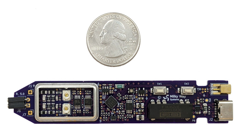
A differential probe, a device for measuring the voltage between two points in a circuit rather than the voltage between a point and ground, it an extremely useful addition to any electronics bench. Inside such a probe you’ll usually find a fancy op-amp working as a differential amplifier, and for correct operation they require careful adjustment to null out DC bias and achieve the maximum common mode rejection. We particularly like [Craig D]’s probe, because these adjustments are taken care of automatically by a microcontroller.
The analogue path provides a lesson for anyone interested in instrumentation signal path design, with the signal conditioning and compensation circuits feeding an AD8130 differential amplifier. Another amplifier samples the output voltage and feeds it to the ADC in the microcontroller. Common mode adjustment is taken care of by a digital potentiometer chip, and DC offset by the microcontroller’s DAC. Controlling all this is an ATSAMD10 chip, and the power is derived from the scope’s USB interface.
All in all it’s an extremely well-executed device, and one we’d be happy to have on our bench at any time. It’s by no means the first differential probe we’ve brought you, here’s another.


The project and its hackaday.io write-up is simply amazing! It’s not often you get to read about what’s inside a diff probe.
All that is missing is a few words about the input referred noise performance and I’d totally buy one!
Ditto!!!!
Yeah, when I was dabbling around with DIY differential probes, input noise was the factor limiting dynamic range.
Based on chip specifications alone, input referred noise would be around 3mVrms for the 150MHz bandwidth. At output (which has 20x attenuation when used with 50 ohm termination) that would be 0.15 mVrms, which is only slightly more than the input noise on most scopes.
The design also seems easy to adapt to AD8129 which has 10x gain and lower noise, in case you want to measure e.g. current shunts.
I believe what’s limiting the noise in this case is not the amplifier.
The input impedance seen by the AD8130 is around/slightly below 2x34k, which would result in thermal noise density of around 33 nV/sqrtHz, which is about three times higher than the input referred noise of the AD8130. This would put the input referred noise of the probe more in the 8 mVrms range.
If I am not wrong that means changing the amplifier would only yield marginal improvement.
The impedance on amplifier input is (34kohm || 24 pF) to ground. This has noise bandwidth of 300 kHz, not 150 MHz. At high frequencies the capacitor will shunt whatever thermal noise current comes from the resistor.
The formula in https://en.wikipedia.org/wiki/Johnson%E2%80%93Nyquist_noise#Thermal_noise_on_capacitors gives thermal noise voltage of 13µVrms, which would be insignificant compared to the amplifier noise.
Adapting the design to an AD8129 is an interesting idea!
Thanks for the kind words! I’ve been meaning to work through a noise analysis. I would be an interesting project log topic and good opportunity to get some eyes on the analysis.
If you’d like some independent testing / review of a proto, I could be interested in helping out. I was working on something very similar ( https://hackaday.io/project/181065-modular-differential-probe ) a few years back, until chip shortage killed that project. Currently I’m so busy with other stuff that I’d be happy if there was a cheap low-voltage differential probe that one could just buy!
Thanks for your support. I will definitely keep that in mind. It would be great to have more eyes on the design as it matures and I build more prototypes. That is a really interesting diff probe project that you were developing on as well! I’m sorry to hear about your struggles during the chip shortage. I had put the PD150 project on hold for a while too. I recently started testing and documenting, and hope to get back into design and prototyping later this year.
As I work a lot with brushless motor control I designed a small variant of this that had a full automatic self calibration as well as 3 total amplifier channels to look at all 3 motor phases.
Wow! By the look of it, that is one gorgeous bit of design and execution. I continue to be amazed at how much the sophistication level of hobbyists has grown in the 5+ decades I’ve been involved in electronics.