A differential probe, a device for measuring the voltage between two points in a circuit rather than the voltage between a point and ground, it an extremely useful addition to any electronics bench. Inside such a probe you’ll usually find a fancy op-amp working as a differential amplifier, and for correct operation they require careful adjustment to null out DC bias and achieve the maximum common mode rejection. We particularly like [Craig D]’s probe, because these adjustments are taken care of automatically by a microcontroller.
The analogue path provides a lesson for anyone interested in instrumentation signal path design, with the signal conditioning and compensation circuits feeding an AD8130 differential amplifier. Another amplifier samples the output voltage and feeds it to the ADC in the microcontroller. Common mode adjustment is taken care of by a digital potentiometer chip, and DC offset by the microcontroller’s DAC. Controlling all this is an ATSAMD10 chip, and the power is derived from the scope’s USB interface.
All in all it’s an extremely well-executed device, and one we’d be happy to have on our bench at any time. It’s by no means the first differential probe we’ve brought you, here’s another.
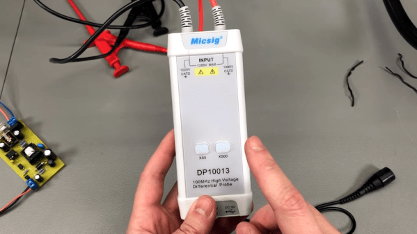
[Voltlog] often looks at interesting test equipment and in the video below he reviews something that isn’t very common in hobby labs: a differential oscilloscope probe. These are usually pretty expensive, but the Micsig probe in the video costs under $200. The question, of course, is what do you need with a differential probe?
A typical scope probe has a ground lead that connects directly to the actual grounding point. This can cause a problem if you try to measure across some component that has more voltage than you want to short to ground. It might hurt your device under test, your scope, or both.
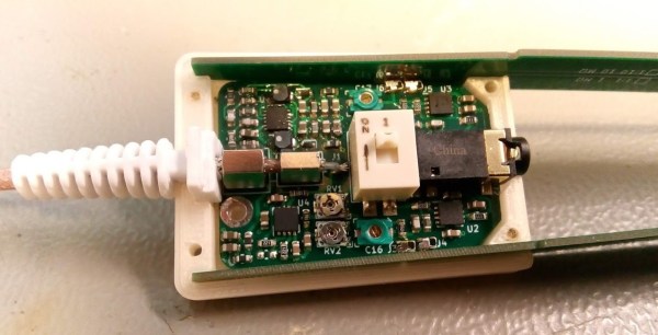
[Petteri Aimonen] presents for us a modular differential probe, as his entry into the 2021 Hackaday Prize.
This project shows a simple and well polished implementation of a differential-to-single-ended preamplifier, which allows a differential signal to be probed and fed to an oscilloscope via a BNC cable.
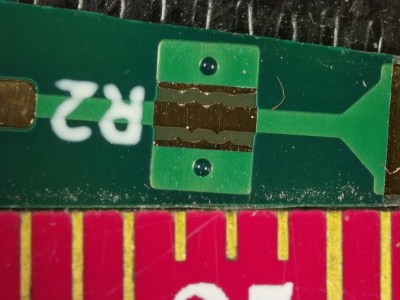
PCB Spark gap for primary ESD protection
It implements a classic instrumentation amplifier, where we have two amplifier stages. The first gives us the options for a gain of either 1 or 10, if we need it, with the second stage having a gain of 2.
The remaining circuit is a power supply to generate the necessary dual-rail supplies to feed the opamps. There is a lot of filtering on those output rails as well as on the USB power input side to try keep all that switched-mode power supply noise out of the signal path.
There are a couple of interesting design choices including the use of PCB material for the long removable probe arms, that integrate PCB spark gaps to offer a first defence against ESD reaching the more delicate parts of the system.
Why This Is Useful
There are two main classes of signals we electronics engineers care about: single-ended and differential-mode.
With the first kind, the signal is carried on a single wire, which is defined as being referenced to the common system ground. Current flows along the wire and returns to its source along the path of least resistance, at least at low frequencies. At higher frequencies, the path of least inductance is more relevant. This is all well and good, so long as you design the PCB correctly.
Coupling from adjacent wires due to mutual capacitance and inductance, as well as noise in the reference ground all conspire to mangle the signal we want to pass down the wire.
As the frequencies increase, and especially if you’re dealing with sharp edges, with all that extra odd-harmonic power, things start to get bad real fast. The way we deal with this is by utilising differential-mode signalling. This is where instead of a single wire, referenced to some notion of ground, we send the signal down a pair of wires, where the voltage difference between the wires forms the signal. Any external noise that leaks into the pair, will (hopefully!) affect both wires equally, forming what we call a common-mode component. When you look at the difference, this common mode noise disappears. (Our own [Bil Herd] covered this some time ago.)
When probing a circuit, it pays to have the right kind of probe as well as an understanding of the effect the probe will have on the circuit in operation. If you have a single-ended signal and you want to view it on your scope, your choice is either a passive or active probe. Usually some kind of passive probe will be most available. These commonly come in 50 Ω and 1 MΩ versions, and you need to be careful to use the correct probe type for your application.
For probing differential signals, it is possible to use a pair of probes, one for each signal wire, and then utilise the scope’s math difference function to show the signal. This is quite often a desperate measure, and what you really want is a differential front-end in hardware. You need a differential active probe.
The circuit may be simple, but don’t underestimate how much tweaking it needs to have good performance – a little slip with the PCB layout, as the author describes, caused some annoying resonances which can be hard to track down.
The project is still under active development, with the author showing the process as the project progresses, but its looking pretty good already, if you ask us.
Sources can found on his GitHib, which uses all Open Source tools, so its pretty accessible too.