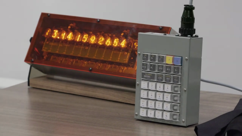
If you like Nixie tubes and/or DIY calculators, checkout this interesting talk from the HP Handheld Conference in Orlando last month by [Eric Smith] from Brouhaha and [John Doran] from Time Fracture. For 20-some years, [Eric] and the late [Richard Ottosen] have been incrementally developing various DIY calculators — this paper from the 2005 HHC conference is an excellent overview of the early project. [John] got one of those early DIY calculators and set about modifying it to use Nixie tubes. However, he got distracted by other things and set it aside — until reviving it earlier this year and enlisting [Eric]’s aid.
This presentation goes over the hardware aspects of the design. Unlike the earlier PIC-based DIY calculators, they decided to use a WCH RISC-V processor this time around. The calculator’s architecture is intentionally modular, with the display and keyboard housed in completely separate enclosures communicating by a serial interface. If the bulkiness alone doesn’t exclude it from being pocket-sized, the 170 VDC power supply and 1/2 W per digit power consumption certainly does. This modularity does lend itself to DIYers replacing the display, or the keyboard, with something different. [Eric] wants to build a mechanical flip-digit display for his unit. As for the software, [Eric] reviews the firmware approach and some future upgrades, such as making it programmable and emulating other flavors of HP calculators.
If you’re embarking on a similar project yourself, check out this talk and take notes — there are a lot of interesting tidbits on using Nixie tubes in the 21st century. If [Eric]’s name sounds familiar, you may know him from the Nonpareil calculator software used on many emulators and DIY calculator projects, one of which we covered some years ago. [John] is also a long-time tinkerer, and we wrote about his gorgeous D16/M HCMOS computer system back in 2012. Thanks to [Stephen Walters] for sending in the tip.


Really good aesthetic on this one, feels like the real deal
I never, ever, wanted to know what an industrial calculator would look like, but I’m very impressed with the effect! It looks exactly like an industrial calculator!
That reminds me, I need to try making my own RPN four-function with an ESP32, a button matrix, and an I2C OLED display…
Wang did it :-) (but not as an RPN calculator). As a kid, I used to love using it at the Boston Museum of Science in the late 60s. IIRC it was a main controller and four keyboard/Nixie UI terminals.
https://www.oldcalculatormuseum.com/wang360.html
In the late 70’s early 80’s the Boston museum had some big machine in a plexiglass box that had nixies….and was RPN….because I remember having a hell of a time (I was middle school age) trying to understand the RPN and why anyone would do it in such a complicated way. Fastforward and I use a RPN calculator on my PC everyday
“If you like Nixie tubes and/or DIY calculators…”
That Venn diagram is just a circle.
I want to know where to get those square pushbuttons.
Seconded! That is what really sold it for me. Would love to use something similar on my projects.
There’s a discussion about those buttons in the talk.
They are normal Cherry MX switches, with relegendable keycaps from P.I. Engineering.
https://xkeys.com/xkeys/accessories/keys/keycaps.html
I printed the legends onto inkjet-printable vinyl stock and cut them with a Silhouette Cameo 4 cutter. I wrote a C++ program that generated the print and cut files as PDF. The tricky part was getting the cut shape to match the shape of the keycap; for a basically square keycap it was a bit of a surprise that the legend surface is curved. P.I. provides PDF templates, and I manually extracted the geometry from those.
Thank you for the detailed reply. Great project!
Beautifully done, Gentlemen!
Perhaps if you send me the details of the protocol used to talk between the keyboard and display, I could make a keyboard unit that emulates a Wang 300-series calculator.
I assume the CPU for the system is in the main unit, and there is some brains in the keyboard that scans the keys and sends the key presses (hopefully signals for both pressed and released for each of the keys) to the main unit? You mentioned slide/toggle switches being a possibility on the keyboard unit. The Wang calculator has four of them, one which is a power switch for the keyboard display unit, which would need to tell the main unit to ignore any keypress signals and blank the display until it is turned on. The other switches determine various accumulation modes, and the main CPU would need to be able to sense their state.
One oddity of the machines is that pressing the [CLEAR ADDER] key would result in a display of “+”, with all of the rest of the digits blanked. I assume there’s a way that could be displayed? I see that digits to the right of a number being input are blanked, so there has to be a way to blank individual digits, perhaps with an “out of range” BCD code like 1111.
I suspect that your math package could be used, although the Wang 300-series calculators did multiplication and division, as well as square root and x^y using logarithms, and had guard digits that it would use (four beyond the ten displayed) that would round the results so that 2 x 2 would not end up giving 3.999999999 as a result.
I’d have to do timing measurements of the real thing as accurately as I could to make the emulation take the same amount of time to complete calculations, as well as some form of rapid display updating with “spinning digits” that simulated the unblanked display while the machine is calculating. Would that be possible to emulate by rapidly updating the display quickly with random digits? It wouldn’t be an exact emulation as the digits that spin kind of make sense based on the calculation, but emulating that in detail is difficult, if not impossible.
Thanks for the details on those key switches and keycaps. I’ve long looked for a good key switch with replaceable keycap legends, much like the original Wang calculator keys (they used paper legends under a clear keycap), with a plain old microswitch under the keystem. It worked and aged well, and it was inexpensive and reliable.
Again, congratulations on a fantastic project with such an amazing result!
The microcontroller is in the main unit, with the display and power supply. What we currently have is a bare 5×8 switch matrix wired in full between the keyboard and main unit. The intent was to use USB with HID class, and a sceond microcontroller in the keyboard, but we haven’t yet switched to that.
The display digits are as you suggest blanked by non-BCD digits. The leftmost and the third from the right tubes are +/- tubes for the signs of the significand and exponent.
The “math package” is the microcode trom the HP-32E ROMs, running on a simulator for the HP Woodstock architecture. For a new calculator design, rather than a microcode simulation, one could use any math library written in C, such as the Intel decimal library, or Mike Cowlishaw’s decNumber. The microcontroller we used does have IEEE single precision binary floating point hardware, but for obvious reasons that’s not suitable for a calculator.