Humans are walking high voltage generators, due to all the friction with our surroundings, wide variety of synthetic clothes, and the overall ever-present static charges. Our electronics are sensitive to electrostatic discharge (ESD), and often they’re sensitive in a way most infuriating – causing spurious errors and lockups. Is there a wacky error in your design that will repeat in the next batch, or did you just accidentally zap a GPIO? You wouldn’t know until you meticulously check the design, or maybe it’s possible for you to grab another board.
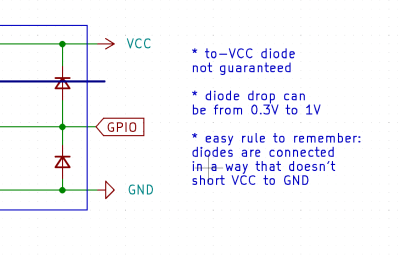 Thankfully, in modern-day Western climates and with modern tech, you are not likely to encounter ESD-caused problems, but they were way more prominent back in the day. For instance, older hackers will have stories of how FETs were more sensitive, and touching the gate pin mindlessly could kill the FET you’re working with. Now, we’ve fixed this problem, in large part because we have added ESD-protective diodes inside the active components most affected.
These diodes don’t just help against ESD – they’re a general safety measure for protecting IC and transistor pins, and they also might help avoid damaging IC pins if you mix. They also might lead to funny and unexpected results, like parts of your circuit powering when you don’t expect them to! However, there’s an awesome thing that not that many hackers know — they let you debug and repair your circuits in a way you might not have imagined.
Debugging Wiring And Chips Alike
Here’s a simple scenario. You have a button connected to your Arduino, with some long wires, maybe it’s even on a screwy breadboard. One pin is connected to ground, and another is connected to a GPIO. You press this button, and nothing happens in your code. Why is that?
First, you’ll want to verify your connections. Arduino-internal ESD diodes let you do that with a single measurement at the button. Put your multimeter into diode test mode (or low-resistance measurement mode), then reverse your multimeter leads, putting the red lead on ground and black lead on the button pin. Then, touch the button pins and see if you can sense an internal diode – if not, your wiring is likely suspect.
This is not all, however. Do you have a broken PCIe GPU? It can be overwhelming – many things could be broken, where do you start? It could be the GPU chip itself, it could be one of the smaller memory chips, or it could be the VRM. An ESD diode test helps yet again. Put the red lead on GND, and check the card edge pins with PCIe diffpairs, probing behind series capacitors where those are present near the card edge.
The results are stunning – you can notice a GPU core chip failure that you wouldn’t normally. It’s simple – card edge-connected GPIOs will have a certain kind of voltage drop, and the PCIe link will also have a certain voltage drop, just a different one, because high-speed links need different ESD diode structures.
If one or few PCIe pins or GPIOs deviate from the PCIe or GPIO ESD diode value on all other pins, you might just have a broken core – this knowledge will save you a hefty amount of time if you are thinking of reballing the GPU or fixing some other areas like the VRM. It’s a super efficient way to test your tech, and of course, it works for other things like ICs.
There’s more – you are probing a board, and you want to know where a resistor goes. Is it a pull-down resistor, is it connected to some external connector, or is it part of some analog circuit? With red lead on ground again, check if there’s a diode – that’s how you can know it’s connected to a digital input of some sort, or floating.
Powerful, Simple, Friendly
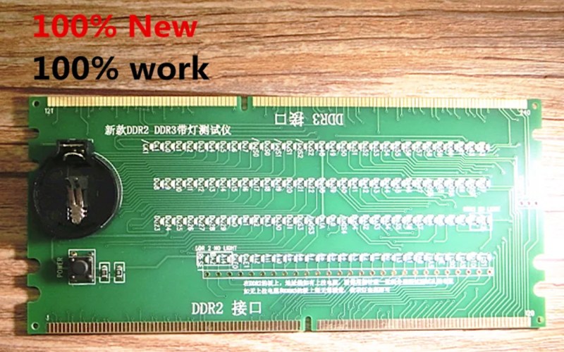
 Would you believe me if I told you there’s more? If you’ve ever browsed AliExpress for devboards or PC tech, you have likely seen these adapters with tons of LEDs and a battery board. These are tester boards for PC components, they are beautifully analog in how they operate, and it’s insanely easy to build your own – let me show you how.
Yep, these testers also test the presence of ESD diodes. Furthermore, the LED will shine with different brightness depending on the nature of the connection. It’s seriously awesome in how quickly you can test things at a fundamental level with these boards. If your desktop’s CPU doesn’t boot, it might just be a broken ball in its LGA socket, and plugging such a tester in will save you a metric kiloton of trouble debugging other things.
They are dead simple, too. If you want to test 20 or 200 connections at once, you only need a CR2032 battery and a bunch of LEDs – maybe some series resistors, but even those don’t seem necessary to me. The coin cell batteries have an internal resistance of their own, which helps us because we don’t need per-LED current limiting resistors – you can just shower a board in LEDs, add a coin cell holder, and make it into a debugger for anything.
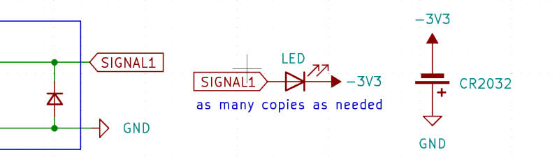
As a USB-C zealot, of course, I’ve made a USB-C tester – and immediately tested it on some of my broken or mysterious USB-C ports, to great success. Here are the KiCad files, complete with a very broken-looking schematic.
For a start, this lets you check if any USB-C port you’re working with, is USB2-enabled or not. Is that docking station port “charger-only”, or can you also plug a flash drive in? The default answer is “charger-only”, but here, you can check for sure. However, it doesn’t end here – such a tester will give you an analog-ish value the same way that a multimeter test would!
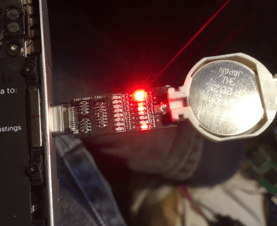
The LED brightness will vary depending on what’s connected to the pin. For instance, is this CC pin connected to an IC digital pin, is it a dead short to GND, does it just go to a pull-down resistor, or is it disconnected? This tester will show you all through LED brightness alone. It’s hard to see on the pictures, but your eye will be able to distinguish between different pins and their roles, and there’s something deeply beautiful about it.
Is your USB-C port mechanically screwy, perhaps? Or is it just that a CC pin on it is shorted, and that’s why it only works in one orientation? Maybe one of the USB3 data pairs is broken because a capacitor flew off? I’ve already managed to debug all of these cases, using this board to fix a few dead USB-C ports.
Why So Unpopular?
By now, I’m seriously confused why we never saw such a tester for, say, MicroUSB ports. How come? It’d be super easy to have LEDs for VBUS, D+, D- and ID, with the ID pin LED telling you immediately whether the MicroUSB port on your smartphone is capable of OTG mode, and it’d cost about $1. There’s no shortage of RAM and CPU testers on Eastern platforms, and repair shops have long adopted them, but the hacker world is missing out on some tiny fun peripherals that are within the reach of our fingertips.
In short, internal ESD diode testing is a severely underappreciated hacker tactic. Whatever you want to do, whether it’s PC component repair, or checking cables, or testing your boards for shorts after reflow, probing for ESD diodes is easy, and can give you insights at the speed of light.


1970s TTL and NMOS were not so vulnerable to ESD, too.
It was early CMOS and DRAM which were vulnerable to ESD. Modern CMOS has protective-circuits built-in to compensate for this design flaw.
A good read!
On-die ESD protection diodes are a fascinating topic overall. Industrially, in PCB assembly processes, ESD diodes are exploited to verify connectivity in automated flying probe or bed-of-nails/ICT testers. They follow the exact same methods as the article describes with a multimeter, just wayyy faster.
Another hint is that you can determine what kind of ESD protection structure is on a given pin by looking at the Absolute Maximum Ratings in a part’s datasheet. Typically most power pins are only protected by a Zener or FET “clamp” or “crowbar” protection circuit to ground.
For instance, if a given pin is stated as “ADC_INPUT GND-0.3V to 5.5V” then that pin is likely protected by just a Zener diode or FET ESD protection structure to ground. However if it states “ADC_INPUT GND-0.3V to VDDA+0.3V” then that particular pin is protected by both a diode from ground to ADC_INPUT but also a diode from ADC_INPUT to the power rail (VDDA), aka “Steering Diodes”. This is extremely important and exploitable for circuit designs, especially when dealing with cross-power-domain signalling. For instance, if you’re designing a level shifting circuit, using an input on an IC that’s only protected by a Zener/FET ESD protection structure to ground will be preferable/advantageous compared to steering diodes. Of course, respect the absolute maximum ratings (really, you should respect the recommended operating conditions first and foremost).
Backdriving (feeding power into a pin that then powers the device) is a big no-no for normal operation, so you’ll typically want to avoid it. Butttt, if there’s no other way and you have to backdrive for circuit operation. Try to keep the DC current flowing through the steering diodes from the I/O to VCC or Ground below 1mA (really below 100uA) as this’ll limit the electromigration aging effects alongside minimizing steering diode self-heating.
As a last aside, most integrated ESD protection diodes are really only intended to protect against ESD in ESD controlled environments (e.g. static strap benches or anti-static factories) per HBM, CDM or MM ESD models. In the real world with uncontrolled environments, you’ll need more protection to survive say IEC 61000-4-2 ESD.
Here’s some articles I’ve always gone back to on the topic. Hope they’re useful to you too!
https://www.analog.com/en/analog-dialogue/articles/esd-diodes-as-voltage-clamps.html
https://www.analog.com/en/technical-articles/esd-protection-for-io-ports.html
https://www.ti.com/lit/sg/sszb130d/sszb130d.pdf?ts=1702580241410&ref_url=https%253A%252F%252Fduckduckgo.com%252F
https://www.youtube.com/watch?v=2yFh7Vv0Paw
good post, steering diodes wasted months of my time :)
Perhaps the worst type of ESD damage is that which weakens a junction or a MOSFET gate insulating layer without causing immediate failure. These can result in anything from flaky behaviour to (sometimes very) premature failure down the road.
Great article Arya! I’ve spent years in silicon validation and I never knew about using TVS for connectivity checks.
You can also use this for checking if that QFN or BGA you just hand-reflowed actually has all its pins soldered down to the PCB.
Worse in the past?
That would require objects to ignite when in proximity to my techno-haunted house.
I have monitors that will shut off if I don’t ground myself before touching my chair, which is not even touching the table.
I have a computer that reboots if you move your hand within 1m of it or the keyboard/mouse without grounding yourself.
I even have a haunted Arduino that will start vomiting random characters over serial and or outputting squealing noises from the audio port.
I keep the house at 45% humidity, don’t have any carpet, and no ground faults.
I had two different electricians check my wiring and recommend a priest…
You might just have to get metal flooring and ground it, then walk around in bare feet to just about always be grounded.
WAY back in the day (’92 or so) I had a computer (80286 or 80386) that had fried a parallel port on an ISA card. So I replaced it (and this was like a $30-40 part back then so not exactly pocket change. In today’s pricing, maybe $70-85 or so.) Well, it fried again a couple of days later so I left it for a while and just did without the printer. Then maybe a couple of weeks later, I turned on the vent fan in the bathroom and the printer in the other room reset like it’d just been turned on. I turned off the fan and back on and, again, the printer reset. So I just unplugged the vent fan up in the housing and replaced the card again and never had another issue with it.
I used this technique to distinguish between typical GPIO and I2C bus when it comes to chip / hardware reverse engineering. Also helpful for BGA/QFN assembly validation too.
I had a job in the early 2000’s, a temporary position but 40 hours a week for over a month, just replacing the FETs for a contract manufacturer who used the cheapest fets they could buy and had poor esd safety, so every single one of their boards had the through hole switch fets dead from gate damage. I spent all day replacing them while actually grounded working on a grounded workstation, and got their whole order repaired, so it wasn’t THAT long ago that people were still working with fragile fets in somewhat mass production.
Cool! Thanks for sharing!
It does sometimes get a little more complicated: https://ww1.microchip.com/downloads/en/AppNotes/93013a.pdf
And if you’re doing some temperature testing on a product and have some GPIOs coming out of your thermal chamber, say a UART, you get a free temperature sensor ! right inside the enclosure of your product, at the PCB level ;)