Last time, I talked about racing the beam, a type of graphics used when memory was scarce. Now it’s time to step into the future with more memory and talk about what modern 2D games still do to this day: rasterization.
Just in time Memory
Continuing the trend set by racing the beam, rasterized graphics are also on a grid, just a much tinier one. Though not unique to rasterized, the “frame buffer” is the logical conclusion of bitmap mode fidelity: enough memory is allocated so that every pixel can have its own color. What’s different about a frame buffer is that everything is drawn before it is shown and, crucially, this doesn’t have to happen in the same order as the pixels are displayed. Rasterization draws entire shapes — triangles, lines and rectangles — into the frame buffer and the screen is typically updated all at once.
Crude Circles
 You may have noticed I didn’t mention circles earlier. That’s because we don’t actually draw circles, we approximate them. It’s a simple thing, really: Would you rather draw 50 triangles, or compute 10000 distance calculations? Well, if you said triangles, the computers agree with you.
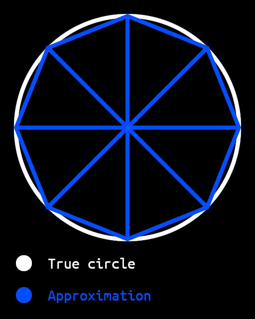
This diagram shows an exaggerated representation of how a circle can be approximated using triangles. It’s quite obvious here where the triangles are, but the more triangles you add, the closer you can get to a perfect circle. More complex shapes, like text, polygons and abstract shapes can also be made with triangles.
The plotting predicament
 But approximating circles isn’t the only problem in rasterization, approximating triangles is a problem too! There are a limited number of pixels, which means that all but a perfectly aligned rectangle needs to be approximated in the actual rasterization process.
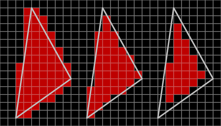
There are several ways to rasterize triangles, from left to right: any pixel that touches the outline of the triangle, any pixel whose center lies within the triangle, or any pixel that lies fully within the triangle. The second (or center) one is most common, because it avoids both unnecessary overlap and unnecessary gaps, notable artifacts of the other two methods respectively. Unnecessary overlap causes semitransparent shapes to show a seam of more opaque pixels, while unnecessary gaps cause most shapes to show a seam of unplotted pixels, both of which are undesirable.
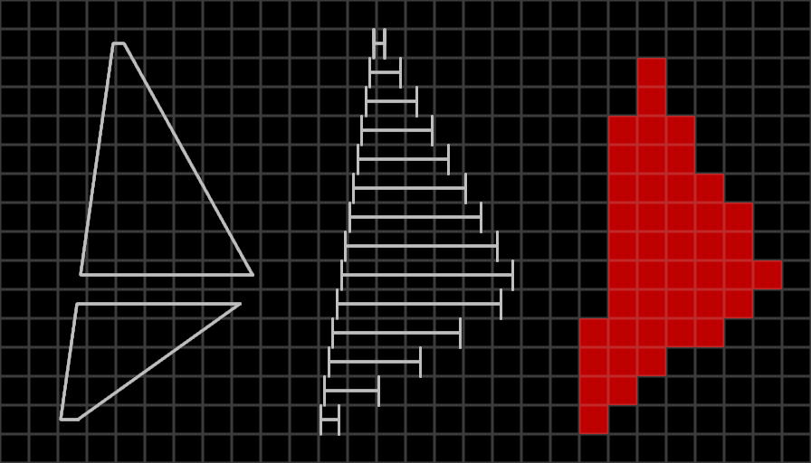 Now that’s nice and all, but how does a computer actually implement such a thing? My computer graphics library does it with linear algebra. First, I divide the triangle into one or two trapezoids with a horizontal top and bottom line. Then, I divide it into imaginary horizontal lines at the vertical center of each row of pixels. Finally, I plot pixels from left to right within these horizontal lines.
Rectangles and lines are simpler: rectangles always have two horizontal and two vertical edges so they can be drawn with two for loops and lines are usually drawn by simply linearly interpolating between both endpoints. All other shapes can be drawn using these three primitives like I said earlier.
Colorful math
Since the switch to framebuffers, we can specify the color per pixel without having to use a palette, like when racing the beam. This opens up the possibility for semitransparent shapes, some ways of drawing text, images and even shaders.
 Shaders are programs that run in the GPU, but what most people think when they hear shaders are actually fragment shaders. Also known as pixel shaders, they’re used to calculate the color of a single pixel in the shape.
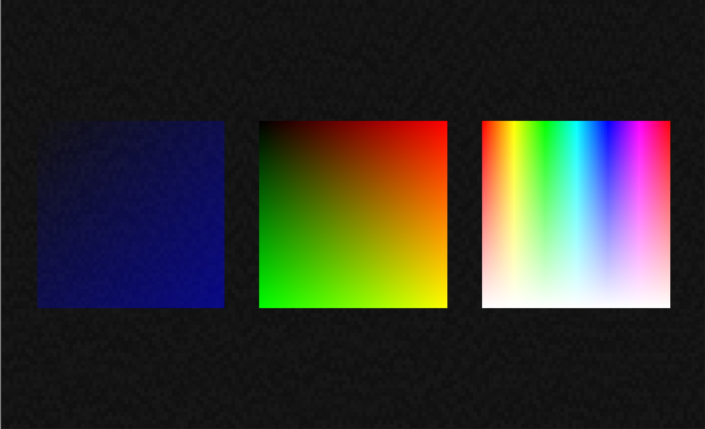
Most fragment shaders use texture coordinates, also known as UV coordinates or UVs, as the primary variable. Be that to literally apply a texture (i.e. an image), or to change the color (right). UVs range from 0 to 1 and are used primarily for images. The square in the center shows its UVs by making U (left to right) red and V (top to bottom) green. The other two squares show effects that are possible using UVs, which is of course changing the colors.
Conclusion
Rasterization is a rendering technique that takes advantage of the large amounts of memory afforded to computers. By its nature, it takes much better advantage of parallel processors in the form of GPUs and is a lot more flexible than racing the beam. Using rasterized graphics, you can draw almost anything, from a simple circle to a complex webpage. Rasterized graphics are flexible and used everywhere today.
Stay tuned for next time, when I’ll spice things up with matrix math, more images/sprites and multiple layers!


Hmm.. did all this start back in the 70s, 80s and 90s. It sounds like you may have missed optimizations based on Duff’s device and the many versions of Bresenham’s algorithm. N dimensional B’s algorithm is great for color interpolation of spans and edges. Also for z values and alpha values should you need them. And the circular version makes generating end points for the spans of a true circle fast and easy.
Btw, use fill strategy 1 on the left edge and 3 on the right to avoid filling any pixel more than once.
All of this did start in the 70’s through the 90’s, but what was relevant back then has little now unless you’re still doing your drawing in software. Even GPUs tend not to rasterize geometry by edge walking, and the interpolation of per-vertex parameters is handled almost entirely transparently to the person writing the application or even the shader code (you can, of course, request derivatives of each along X or Y).
Duff’s device and Bresenham’s algorithm are just not that relevant these days; they were clever optimizations during the time that they existed, but Bresenham itself is relevant now that even lines are largely treated as polygonal geomtry. It’s not the early IrisGL days where accelerated hardware lines were a big selling point.
As someone who’s been in the game industry for 18 years now, as well as spent a couple of years in renderer programming particularly, it’s interesting to hear how much of this advice continues to apply, and how much of it applies more to hardware from 10-15 years ago.
These days, for text you’re more likely to rely on a library like Slug – which can provide a set of tesselated geometry based on the font paths themselves, in which case you’re still doing rasterization (just one step removed) – or you’re just drawing an aligned quad per glyph, with the individual glyphs baked into an atlas at build time.
GPUs nowadays also rely much less on edge-walked rasterization and instead parallelize from the outset: A massively parallel point-in-triangle test is, apparently, more efficient at this point than bottlenecking on walking the edges of each primitive processed by the vertex shader stage.
Nice to see that professional game engines also suck natively with fonts.
NEVER use the native font in Godot. Just don’t. I’m sure there’s a law against it coming at some point.