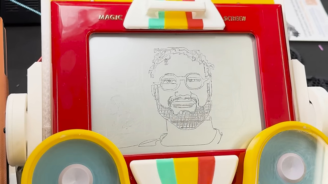
We’ve covered etch-a-sketch robots before, but usually they’re not quite as fast as [Every Flavor of Robot]’s “video” etch-a-sketch, capable of drawing a full portrait in as little as a minute.
Continue reading “Drawing Videos On An Etch-a-Sketch”

We’ve covered etch-a-sketch robots before, but usually they’re not quite as fast as [Every Flavor of Robot]’s “video” etch-a-sketch, capable of drawing a full portrait in as little as a minute.
Continue reading “Drawing Videos On An Etch-a-Sketch”

Some of you may know there’s a version of UNIX for the Commodore Amiga, aptly called Amiga Unix or AMIX. There is an almost complete record of versions from 1.0 to 2.03, but 2.02 was lost media–until [Forgotten Computer] found it on an old Amiga.
It starts with an auction held for the 40 year anniversary of the Free Software Foundation where, by just one second, the highest bidder was too late. What do you do first with an artifact as valuable as an old FSF computer? You image the hard drive. Then you make several copies, including on different computers–after all, you wouldn’t want to lose the data on it. Preservation secured, the natural next thing is to boot it–and that’s when we see the magic 2.02c version number.
According to thorough digging by [Forgotten Computer], this version was–until now–lost.
In the video after the break, [Forgotten Computer] goes over what Amiga Unix is, the discovery process, and explores what’s on the disk–including FSF staples like GCC, G++ and core utilities like GNU less.
Continue reading “Lost Version Of Amiga Unix Suddenly Reappears”

If it’s summer in a warm, humid climate, bugs can be the bane of your existence. A natural solution is to place a passive bug zapper to catch bugs at night. But what if that isn’t fancy enough? [Nicolas Boichat] spices it up with a passive bug zapper that tracks its kill count.
But how exactly do you detect a bug zap? With an antenna, of course! When a bug gets caught, it arcs, creating an electromagnetic pulse. A small loop antenna on the backside of the zapper receives the signal.
Continue reading “Passive Bug Zapper Tracks Its Kill Count”

Nearly all modern PCBs are designed with the help of EDA software, but not all of them. [ALTco] shows us the process of plotting out a board the old-fashioned way — by hand.
Back in the day, drawing out the traces on a PCB lead to beautiful, smooth lines that [ALTco] wanted to imitate. But first, he needed to figure out how the rest of the fabrication process worked. He starts by just experimenting, both with the “resist” markers and paint, and the etching compound. Things rarely work first-try, and neither did his home-made etchant. So then it was time to buy some ferric chloride, the standard copper etchant for PBCs. A few more tests sorted out which permanent marker worked best.
[ALTco] starts by thoroughly cleaning a raw copper-clad board so the marker sticks properly, then draws the circuit for a little analog fan controller. The board is then laid in a bath of the etchant for several minutes while gently rocking it to keep the reaction going. Finally the board is taken out, etchant stored for re-use, and the board washed with water and then presumably IPA to remove the remaining marker. Some assembly of the newly-printed circuit board later and you have a cute little smoke absorber for your soldering projects.

Most people take the Moon for granted, not considering its slow cycle where the sun gradually illuminates different parts of it. A recent project from [Karsten Mueller] helps you keep our nearest celestial neighbor in mind by putting a tiny version on your desk. (German)
The device itself is made with a circular display, an ESP32-S3, and a simple 3D printed case. But the interesting part is the software — it’s not just a moon phase display, it actually takes your local time, latitude and longitude into account. The resulting image is an approximation of what the moon looks like if you were to look at it, even if you wouldn’t actually be able to see it, such as when it is obscured by the Earth or barely visible during the daylight sky. Initially the project actually used a photograph of the Moon that [Karsten] personally snapped, but there’s also an option to pull the imagery from NASA.
The original write-up is in German, but there’s also an English page for the project on Hackaday.io, and the source is available on GitHub if you’d like to put one together yourself.

Custom printed circuit boards have become more and more accessible to the average hobbyist over the last decade. But one problem still remains: your circuits will take at least a couple days to make. But what if you needed some really rapid prototypes? [The Raccoon Lab] shows us how to do it with a 3D printer.
You start with the usual hobby PCB pipeline: take your idea, make a schematic, and then lay it out in KiCad. That’s where the changes start: to keep traces strong, they are made very thick. The PCB is then exported and opened in 3D CAD software, where the traces are extruded to be 2 mm tall. Off to the printer! The newly printed “circuit board” is made conductive by applying copper tape to it, and traces are cut out along their raised edges.
The result is a very quick and dirty PCB. Sure, it isn’t exactly production-ready, but for just about any simple microcontroller project it’ll do just fine, and it’s a whole lot more accessible than milling one using a CNC! We’ve seen a few variations on this approach recently, including some custom software designed to help along the process.
Continue reading “Using 3D Printers To Make Circuit Boards”

As we learn more about all the nasty stuff floating in the air, it becomes more compelling to monitor the air for pollution levels. [Aleksei Tertychnyi] does just that with pollutagNode2, a solar-powered pollution sensor.
The device uses a Seeed Studio Wia-E5 module for its built-in LoRa low power long-range communication capabilities. Pair that with a cheap 2 watt solar panel and a Li-ion battery, and you have a monitoring device that can stay up indefinitely — or until harsh weather gets the better of it. Even if the solar panel were to be omitted, a full charge would last you about two weeks!
It comes on an open-hardware PCB; no need for giant wire messes, just solder the solar panel, battery, sensor, and anything else you want onto the convenient pads on the side. It also integrates into the existing sensor community nicely via existing LoRa infrastructure. All this combined makes it easy for anyone to deploy one.