Using computers that feature a high-resolution, full-color graphical interface is commonplace today, but it took a lot of effort and ingenuity to get to this point. This long history is the topic of [Dr. Jon Peddie]’s article series called The Graphics Chip Chronicles. In the first of eight volumes, the early days of the NEC µPD7220 and the burgeoning IBM PC.
These are just brief overviews of these particular chips, of course, with a lot more detail to be found when you go digging. Details such as the NEC µPD7220 being the graphics chip in Japan’s PC-9800 series of computers which are famous for the amazingly creative art and games that this chip enabled.
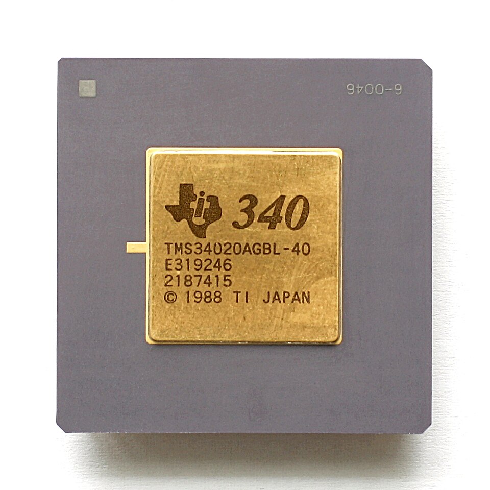
While the average Hackaday reader is likely familiar with the IBM PC side of things, Texas Instruments’ graphics controllers, including the very interesting TMS34010 and successor TMS34020 which can be called the first proper graphical processing units, or GPUs, effectively a CPU with graphics-specific instructions.
Although it’s tempting to see computer graphics as a direct line from the days of monochrome graphic controllers to what we have today in our PCs, there were a lot of companies and countless talented individuals involved, including companies who built clones that would go on to set new standards. If you’re into reading through a few years worth of computer history articles by someone who has been in the industry for even longer, it’s definitely worth a read.
Thanks to [JohnS_AZ] for the tip.
Top image: NEC µPD7220 by Drahtlos – Own work, CC BY-SA 4.0)