A triboelectric nanogenerator (TENG) certainly sounds like the sort of thing you’d need to graduate from Starfleet Engineering to put together, but it actually operates on the same principle that’s at work when you rub a balloon your head. Put simply, when friction is applied to the proper materials, charges can build up enough to produce a short burst of electrical energy. Do it enough, and you’re on the way to producing useful power.
In a recent paper, [Leo N.Y. Cao], [Erming Su], [Zijie Xu], and [Zhong Lin Wang] describe how a functional TENG can be produced on a standard desktop 3D printer. What’s even more impressive is that the method doesn’t appear to require anything terribly exotic — just some commercially available filaments and a bunch of PTFE beads.

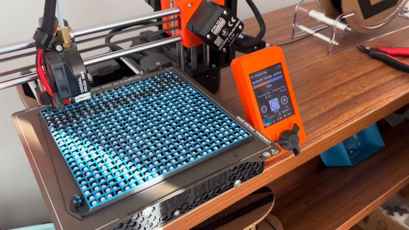
So how do your print your own TENG? First, you load up an electrically conductive PLA filament and lay down a base into which a series of channels has been designed. At around the half-way point, you pause the print to insert your PTFE beads, and then swap over to standard filament for a few layers to produce an insulator. Finally, you pause again and switch back over to the conductive filament for the rest of the print, encasing the beads inside the structure.
As [Leo N.Y. Cao] demonstrates in the video below, you then clip leads to the top and bottom of the print, and give it a good shake. If everything went right, LEDs wired up to your new high-tech maracas should flash as the PTFE beads move back and forth inside. But there’s a catch. Going back to the balloon-on-the-head example, the effect at play here produces high voltages but low current — the paper says a TENG containing 60 beads should be capable of producing pulses of up to 150 volts.
Naturally, you won’t get very far with just one of these. Like other energy harvesting concepts we’ve covered in the past, such as vibratory wind generators, it would take a bunch of these working together to generate a useful amount of power. But given how cheap and quickly these printable TENGs can be produced, that doesn’t seem like it would be too much of a challenge.


Would be interesting smacking one of these on an engine. Using the vibration of the engine to get power.
Sure getting power straight from the engine would make more sense but you might not want to do that.
Sure, and you can use the harvested power to electrolyze water and make fuel for the engine. Free infinite energy!
I knew limitless energy was just around the corner.
Yes! The problem is that corner is at the universe frontier!
The laws of thermodynamics dictate that the additional stress of having to vibrate additional material would negate any energy creation (unfortunately).
Actually, doesn’t having more inertial mass on the engine block mean that it resists torsion in the opposite direction of the output’s angular motion? We might cause a higher max torsion on the linkage, shortening the lifespan, but I mostly just see an effective dampening of harmonic vibrations. Imagine putting that energy into a semi truck’s batteries instead of vibrating the poor driver’s bones to pieces.
Vibration isn’t something the engine has to do; it is a waste product, just like heat.
Excellent insight! Yes, capturing waste vibrational energy, but similar to adding solar on vehicles, what’s the form factor that makes most sense? You’ve seen http://www.Apteramotors.com ? Lighter, AutoCycle (drop a wheel, composite body, in wheel hub motors, extreme aerodynamic + large solar area.. now collect/ dampen vibration as well?)
That would only be true if the engine was already absurdly efficient. The laws of thermodynamics don’t prohibit making something inefficient very slightly more efficient.
And I would imagine the utility would primarily be to extract a bit of energy from the engine without needing to change the mechanical components anyway, not to extract more energy from the fuel or whatever.
I would think that at least a little of the energy harvested would be energy that would have otherwise been released into the air as noise. Too little to be useful? Probably. But not a violation of thermodynamics.
Better vibrations from an overcaffinated teenager.
It could be a useful way to harvest more energy from an engine. Perhaps you’re charging a battery direct with the engine, you could also slap a few of these on the engine and plug these into a separate battery to charge. Maybe even use the thermal energy given off from the engine to charge another battery. There’s so much more energy we could be harvesting from an engine.
IIRC a similar idea is used for passively detecting equipment failures in factories etc, you stick a wireless transmitter that harvests power from vibrations onto a machine that tends to vibrate.
When it misses a ping or the ping intervals have a change in trend, you know something about that machine needs to be checked.
Saves you the effort of finding a point to wire the transmitter to.
Or have it transmit when it powers up – on vibration. Cool battery-free sensors for automation and tracking.
It was 1954 when I was in sixth grade that I was schooled on the laws of thermodynamics. It seems that they have not gained much traction in the interim. Thanks Mr. Lawrence it wasn’t wasted on me.
Hi guys, I am the first author of this paper. Sorry to hijack the top comment and thank everybody for the comments.
No idea why it takes so long for me to find out this post!!
I would love to answer any questions here or through my email/Reddit/YouTube channel (not sure if links are allowed here and can be found in my YouTube Channel).
Here I will answer several questions that are frequently asked.
1. We don’t use energy to generate energy. We aim to harvest wasted energy, such as mentioned ubiquitous vibration energy like from engine or wobbling ocean wave.
2. Engine vibration is harvested in many papers already since TENG was invented in 2012. Thank you guys.
3. Very professional questions about the polarity in the system. In our microbeads system, PTFE beads are always negatively charged, and conductive PLA will induce positive polarity when PTFE approach. As long as the beads move synchronized, the output is great. In fact, we make the channel as small as possible to maximize the synchronization.
4. The current output for a handheld energy pack is crazy, up to 8000 volts that can shock my fingers constantly. Please check my latest videos.
Leo N.Y. Cao
Does this involve enslaving Horseshoe Crabs to make electricity?
Nah just a load of tap dancers. *In my deepest vhs rental preview voice* “In a post apocalyptic world the riverdancer is king.”
How does the polarity of the individual beads line up? If some are +/-, and others are -/+, won’t some beads be working against other beads? What determines where (on the bead) the positive terminal and negative terminal of the charge end up?
Research papers on TEGS (triboelectric generator systems) online show the generator material consisting of 2 layers, so it’s straightforward to harvest the + and – charges from the separate layers.
Anyone know how this is accomplished with loose beads in a well?
Also, if the top and bottom layers are PCB material instead of conductive filament, the power only needs to go through the device thickness’ worth of conductive filament, then across the copper PCB material to the edge, losing much less power from resistive losses.
In fact, if the triboelectric effect is due to beads hitting the top/bottom surfaces, and not the walls, then the walls of the cells don’t need to be conductive at all? Simply 3d-print a grid, add beads, then slap a PCB top and bottom.
This doesn’t seem to be very well thought out, unless I’m missing something?
What aspect of the triboelectric effect am I missing here?
The idea is that, if the beads are in sync with each other, you end up with a consistent AC waveform as the beads move a fairly consistent amount of charge back and forth. In the example, they charge a capacitor by rectifying the power, then low pass filtering (combined with the use of a gas discharge tube to improve the instantaneous current so we can all appreciate the blinkies).
Thanks, but not what I was referring to.
Clearly, AC at the output will be rectified and used to charge something up.
Suppose the bead at A5 moves positive charge in the up direction, but the bead at A6 moves positive charge in the down direction.
In that scenario, aren’t the beads working against each other and cancelling out?
Or to put it another way, take the limiting case of a system with 2 beads (L and R) and consider a single bounce. If bead L moves positive charge in the up direction, and R moves positive charge in the down direction, don’t those cancel out?
What determines the vector of the movement of charge on a triboelectric bead under stress, assuming that the bead is made of a uniform material?
If the direction of charge is determined by the molecular structure of the substance, as it would be for a quartz crystal, then the spheres will be randomly ordered and move charge in randomly ordered directions.
PTFE isn’t a crystal, so what determines the direction of charge movement when it’s stressed?
When you pause the print to put in the beads you have to play a game of Go with an AI to determine the polarity. If it ends up in a perfect Fibonacci spiral you win perpetual motion bingo and Morgan Freeman gives you a prize.
🤣🤣🤣
You mention stress and quartz. I think you’re thinking of piezoelectric effects. Triboelectric is static electricity.
I often turn to quarts when I’m stressed!
My suspicion is that an initially small charge differential sets up a consistent field across the device so that the beads all end up with fields that add up. That may explain why this uses a rather poor conductor mixed with an insulater on both sides instead of a PCB (or it may not, this is all a guess, though one informed by a physics degree and some experience running demonstrations)
IT seems like the plates would polarize and do the charge sorting automatically
I’m going to suggest you Google how a balloon gets statically charged so it sticks to your clothes.. Then you’ll know how this simple gadget works. It’s literally the same idea in theory and practice.. but this is more controlled so the charge is held and useable.
Most intelligent question I’ve read all year. But, seriously, it’s interesting how the static charge lines up in all the balls in the same direction. Any further insights anybody??
While efficiency could be harmed by the issue you have raised, one can assume that most of the spheres will be moved in a similar direction by a mutually experienced vibration or motion, providing a group bias of ‘up’ or ‘down’ charge with each reciprocation, resulting in a net potential difference between the plates that is largely congruent with the direction of each motion.
I.E.- There might be elements working against the group, but the majority will be moving together as, while the motion/vibration being harvested might be random, the motion of each ‘reciprocation’ applies the same force on every element- the majority will be working together at any given moment.
No, it might not be terribly efficient, but if you’re merely harnessing random motion or vibration that is otherwise wasted, this is still a great proof of concept (that evidently works).
LEDs (light emitting diodes) are likely the determining factor in the described application for determining polarity as diodes only allow current to flow in one direction.
The amount of static electric generated is a function of how much friction exists and how far apart the two insulating materials are on the triboelectric scale. The more you increase friction and by selecting materials on the opposite sides on the triboelectric scale the more charge is built up.
I think the two insulating materials here are the beads, which assume one polarity, and the insulating layer that they bounce against, which assumes the other polarity. The beads themselves don’t have positive and negative “sides”.
150V, but how much power in Watts?
Ya still gotta boil water to make electricity.
A watched pot never boils, and if a pot boils and no one there is to see it, does it make electrons?
I think people are thinking too small, rather than the engine block of a big rig, why not line the entire trailer being hauled, it’s nothing but vibration. Or every car in a train or subway or even rollercoasters. The towers that hold up windmills.
Waiting for the earth shattering revelation of the bead shaker that shakes itself, and becomes the runaway thing no one can stop…
I dont know if this uas been suggested before but use active rectification to eliminate a huge point of loss if you run this through any loads other than LEDs
My first thought is the shocks on any vehicle
Yes, on the lower side, obviously !!
If you *did* want to try and use shocks for power, I’d imagine you would just capture some of the energy from moving a magnet in a coil or whatever. A lot of the suspension’s job is to restore the position of the wheel in a moment, using the stored energy from its displacement, so you can’t capture it all anyhow. Getting the best control over wheel position with economical use of material seems better even apart from the energy idea.
Things like exhaust heat or coolant heat seem like better ways to find waste energy. Though highly efficient vehicles often don’t build as much excess heat in the coolant anymore, depending on conditions of course. I guess in a pure-ICE car the other big possible savings would be anything that makes it not a pure-ICE, or at least something that lets it capture braking energy.
Would these produce x-rays in a vacuum? Maybe better/easier than unspooling tape would? There is some XRF tech based on using TEG as an X-ray source.
Vehical minded- what wouldvthe effect be if these were made round and installed on the wheels? This would probably be better for charging due to extended rotation and would also charge when braking.
This is outstanding!
I hope someone will expand on this principle and be richly rewarded.
I am beginning to have great faith in the future with today’s youth.
my big question is , does this really need to be 3d printed ?if i understand correctly its made of 2 sides of an conductive enclosure separated by plastic layer , then woudnt it be much faster and much more conductive to simply form a thin sheet of metal (store bought roll of aluminium or soda can) by pressing it in a 3d printed mould and only print the plastic separator ?
i could see a 10 000 of theses strung togeter and all put ob a large deformable metal sheet , than hitting the sheet like a drum
I wonder if these provide enough static charge for air filtration, such as the charge in a HEPA filter.
The plastic strands in HEPA filters are charged during formation with massive electric charges. Those charges keep the plastic statically charged for the life of the filter, until moisture and stuff eventually neutralize the charge.
I wonder if adding some kind of static generating device to the filter could maintain that charge for longer.