Flexible cables and flex PCBs are wonderful. You could choose to carefully make a cable bundle out of ten wires and try to squish them to have a thin footprint – or you could put an FFC connector onto your board and save yourself a world of trouble. If you want to have a lot of components within a cramped non-flat area, you could carefully design a multitude of stuff FR4 boards and connect them together – or you could make an FPC.
Flexible cables in particular can be pretty wonderful for all sorts of moving parts. They transfer power and data to the scanner head in your flat-bed scanner, for instance. But they’re in fixed parts too. If you have a laptop or a widescreen TV, chances are, there’s an flexible cable connecting the motherboard with one or multiple daughterboards – or even a custom-made flexible PCB. Remember all the cool keypad and phones we used to have, the ones that would have the keyboard fold out or slide out, or even folding Nokia phones that had two screens and did cool things with those? All thanks to flexible circuits! Let’s learn a little more about what we’re working with here.
FFC and FPC, how are these two different? FFC (Flexible Flat Cable) is a pre-made cable. You’ve typically seen them as white plastic cables with blue pieces on both ends, they’re found in a large number of devices that you could disassemble, and many things use them, like the Raspberry Pi Camera. They are pretty simple to produce – all in all, they’re just flat straight conductors packaged nicely into a very thin cable, and that’s why you can buy them pre-made in tons of different pin pitches and sizes. If you need one board to interface with another board, putting an FFC connector on your board is a pretty good idea.
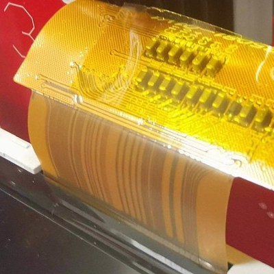
An FPC (Flexible Printed Circuit) is a custom flexible PCB, usually of dark orange colour, same colour as kapton tape. These are fundamentally always a custom design – you can pay to have someone produce your FPC design, just like you would have any PCB produced. You could say that an FPC is really just a PCB that’s very thin and bendy – which makes them wonderful for all sorts of purposes! You can make FPCs for building wearables, medical technology, PCB patches, and you can produce FPCs that act as FFC interconnects if you want better signal integrity, too!
Some people use these two terms interchangeably, but it’s good to know the difference in case you’re getting confusing search results. Let’s go through what it takes to hack on both of these, starting with FFCs and FFC connectors!
Cables Galore
You can find FFCs in many different places! If you’ve ever disassembled a CD/DVD drive, a laptop, a robot vacuum, or a piece of semi-industrial machinery, they’re there, and of course, you’ll know about them if you’ve ever handled a Raspberry Pi camera. You can also buy FFCs in many lengths on the usual marketplaces – even eBay and Aliexpress carry some, there’s a rich assortment at LCSC, and Mouser with Digikey are bound to carry a few. LCSC’s offerings have been the best bang for the buck in my experience, for both cables and connectors, and the usual retailers are pretty okay for one-off FFC purchases. Generally, FFC lengths are somewhat standardized, and tend to come in 5 cm or 10 cm increments. If you want a very specific 12.5 mm FPC in your build, I wouldn’t hold your breath, so maybe plan for some slack.
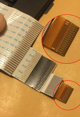
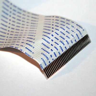
There’s four common pin pitches for FFCs – 1 mm, 0.8 mm, 0.5 mm and 0.35 mm. 1.27 mm FFCs exist but are pretty rare. The larger FFCs have straight contacts as you’ve commonly seen them, and 0.35 mm pitch FFCs have the exposed pins staggered at the connector ends. In fact, 0.35 mm FFCs are most likely to be flex PCBs built for FFC purpose, dark orange instead of white, because the contact staggering seems to require an FPC process to manufacture and can’t quite be done with regular FFC “flattened piece of straight wire” production tech. Still, 0.35 mm is a valid pitch when you’re on the lookout for FFC connectors. FFCs start from four pins – I’ve never seen a two-pin or three-pin FFC, and they appear to be a rarity on marketplaces too.
Beyond pitch and length, there’s a third defining parameter for FFCs, which is orientation. There’s two kinds of orientation – straight, where the exposed pins on both ends are on the same planar side of the FFC, and reverse, where the exposed pins are on different planar sides. This is something to look out for – if you use a straight FFC in a place where a reverse FFC goes or vice-versa, you might end up with either no connection or reverse pinout connection. (And ‘no connection’ is obviously the preferable option here.)
If you’re not interfacing with an already existing FFC, which pitch do you choose? My advice is, pick whichever is the most comfortable for you to solder that still fits in the space you have. Manufacturers seem to stick with 0.5 mm in integrated devices and 1 mm in general devices, with 0.8 mm rarely being used. I stick with 0.5 mm in my more integrated devices, with the caveat that I try and get the connectors to reflow into place with a stencil and solder paste, because hand-soldering 0.5 mm connectors is trickier than 1 mm ones. 1 mm FFC connectors are pretty easy to handsolder, on the other hand!
Connectors All Around
You’ll find all sorts of connectors for FFCs – horizontal, vertical, SMD, and even through-hole connectors for 1 mm FFCs specifically. That is more of an exception – FFC connectors tend to be SMD as a rule. Here’s a sneaky parameter – horizontal FFC connectors can be bottom vs top vs either side contact connectors. This defines which side the connector expects the exposed pins to be on, relative to the board surface – ‘bottom’ is same side as the PCB surface, ‘top’ is opposite of the PCB surface, and ‘either side’ will make contact no matter which side the FFC has exposed pins on. This largely determines whether you need a straight or reverse FFC. If you’ve accidentally picked a straight FFC where you’d need a reverse FFC, swapping a bottom-contact FFC connector for a top-contact one will save you the embarrassment. Vertical connectors also have this alignment – for instance, the Raspberry Pi vertical FFC connectors do.
 Will your FFC fit into a connector? The main question you’d think about would be thickness. However, thickness on both ends is fairly standardized – a typical FFC with blue stiffener strips on each end is 0.3 mm thickness total, so as long as the connector you pick claims to be compatible with 0.3 mm FFCs, and most are, it will fit a generic FFC with blue strips on its ends. Without that stiffener strip, expect 0.1 mm thickness – but it’s rare that you’ll find an FFC without stiffener. It’s always okay to superglue a piece of stiffener from another FFC in a pinch if it breaks off!
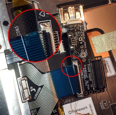
A bigger question is the overall FFC width, and whether it has ‘ears’ – for same pitch and pin count, some FFCs are wider than others! I’ve got bitten by this with a Framework keyboard reuse adapter – both the keyboard and the fingerprint sensor FFCs have extra width on the sides. At least on laptop keyboards, some FFCs even have ‘ears’ meant to mate with the connector, to make sure that the FFC stays in the connector extra securely. If you have to work with such an FFC, you’ll do good paying extra attention to FFC connector datasheets before you click on the ‘Buy” button and solder them onto your PCB!
These are the criteria you need to keep in mind when picking FFC connectors for your board, especially if you’re working with already existing cables. Now, let’s talk about the less obvious aspects of FFCs, that you still should know before working with them.
Handling Instructions
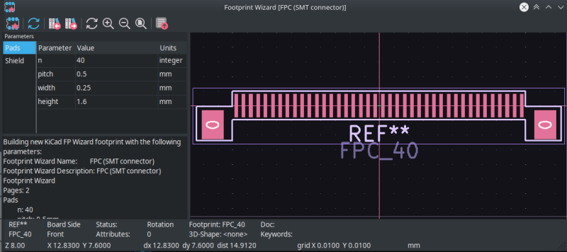
If you want an FFC footprint but Kicad doesn’t have a suitable one in the library, that is actually not a problem at all – Kicad has an FFC connector generator! In the footprint editor, use the Footprint Wizard button (top left corner), which lets you make any FFC footprint with any number and pitch of pins that you could need! On the schematic side, you should use the MountingPin generic connector symbols, and change the autogenerated KiCad footprint pads from `0` to `MP`. I recommend grounding shield pads for the extra mechanical stability alone – it provides no electrical connection whatsoever, of course, so you can do whatever with them safely, but grounding them seems to be a way better choice all around. On cramped boards, grounding the pads also means you don’t impede ground propagation with a huge unconnected pad.
You can bend FFCs, and that’s why we love them. Of course, there’s the usual “have it snake within your enclosure with a pretty liberal bend radius” – an FFC that constantly snakes around like that, will break eventually, but it will live quite a bit until that happens, and you can see that in scanners, FFCs aren’t a failure point we know about.
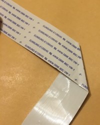
You can even fold the FFC onto itself if you are careful and don’t redo the bend. Usually, folds like this are done diagonally for 90 degree turn purposes. You can even bend an FFC diagonally twice if you need to make a 180 degree turn, or if you need to do an X/Y axis distance change! Of course, keep in mind that sharply bending and unbending an FFC will inevitably break the wires inside of it. If you want to check for broken wires inside an FFC, you can place it in front of a flashlight or a strong desk light – the light will shine through any cracks in the metal.
 You can also solder FFCs to boards in a pinch – however, unless you use low-temp solder, that gets messy fast. Soldering to an FFC with a white plastic covering will quickly melt the plastic – not a problem with FPC-produced FFC with orange kapton backing, but again, those are rare. Also, if you are about to hot air your board, you want to watch out for FFC connectors. They might be a bit more heat-resistant than regular plastic, but that resistance is mostly for short duration IR oven reflow circumstances – they are still, fundamentally, plastic! Cover them with kapton or metal foil or both if you’re about to heatgun your board, just like you’d cover any plastic part, because replacing FFC connectors can be a hassle if you accidentally melt one, and would likely be required.
Last but not least, even if you’re not adding any extra FFC sauce to anything, you still have things to mind. When latching and un-latching an FFC connector, take care – don’t do it from one side at a time, do it at the center or from both sides at once. Breaking off a latch is quite annoying because then you must replace it or bodge it, and they’re finicky to replace, if you even have a spare connector to get a replacement latch from. Same goes for FFC – if you aren’t careful while inserting an FFC into its connector, you can have individual pins dislodge from the FFC plastic and bend away, this is especially easy to cause if you’re working with 0.5 mm FFCs. When the pin bends away, the best case is that it breaks away and disappears somewhere, the worst case is that it bends onto other pins and creates a short-circuit.
On the FFC account, this is what you need to know. Next time, let’s look into FPCs, flexible boards of the printed variety – see where they’re useful, requirements for designing one, and even try to design one ourselves!
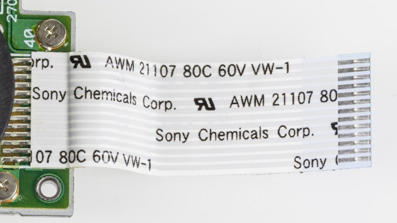
Featured image “Plextor PX-716A – disc drive motor with Sony Chemicals flexible flat cable” by [Raimond Spekking]


It’s a shame there aren’t through hole connectors for FFCs. SMD is great for most parts, but for cable connectors it is always risky, any tugging on the cable can tear the copper pads of the SMD connector’s footprint loose from the FR4 below. Connectors and switches are the two things which should always be through hole.
there are through-hole connectors you can find! you might have seen them in old equipment in particular. downside: they’re usually for large pitches like 1mm or 1.27mm, but that’s about it, and it’s understandable. However, the mounting pads alone are pretty helpful in such connectors, to the point where two-pin JST-PH SMD is way more resillient than its THT version.
There are different use cases for connectors. At the two extremes are:
– Ones intended for frequent unplugging and plugging, by anybody
– Ones intended for very infrequent unplugging and plugging, and only by careful people
Obviously, FFC/FPC connectors are closer to the latter than the former.
As fragile as they may be, they are usually better for the tinkerer than soldered connections.
This! And if you want it to be a semi-permanent connection, something like silicone or (gasp!) hot glue between FFC and PCB can reduce the strain on the connector.
I built an IR Pi camera thingy to watch the hedgehogs who moved into our back yard — and I kept pulling the flat-flex out while I was working on / designing / iterating on the housing. Hot glue. Fixed.
If you’re plugging and unplugging FFC frequently, or subjecting it to too much strain, it’s probably not the right tech.
(I’m totally with you on through-hole USB connectors.)
They have flex cables that are through hole without connectors. Every connection with a removable connection is a point of possible failures.
We used them at MXR and ART to be able to have a break away pcb for the rear phone Jack’s for instrument type cables to reach the rear panel. Put the through hole one the edge of the back of the front pcb part and loop the cable over the phone connectors with the break away where the rear of the main pcb is.
Break a part the pcb after wave soldering and flip the break off pcb and use the phone jack to secure to the rear panel.
Some years back, I was doing a battery replacement on my used phone, and managed to somehow snap the locking tab off the FFC connector for the display. It didn’t just pop off, it went flying. It showed up a day or so later, but I was never able to get it lined up properly to reattach it. And at the time, the idea of trying to spec or replace such a connector was so out of reach that it never even occurred to me. I tried some terrible hacks like taping the cable into the connector, but I never was able to get it to work. RIP phone.
yeah a crucial part of it is that you also need to apply pressure to the cable, pressing it into the metal pins, which the locking tab does. In such a case, finding a piece of plastic of perfect thickness, jamming it in there, and i.e. supergluing it/taping it in place should be sufficient.
Careful. Where the ‘flat’ meets ’round’ tends to be weak. I recommend adding RTV or other strain relief from PCB to the white insulator.
FWIW: The round displays on the 2023 Supercon badge were all of the “kapton” flat-flex type, and they all got soldered on directly by hand. I wasn’t on the assembly line, but I did one prototype version, and it’s not so bad. Another option if you’re feeling too cheap to spring for the proper connector, but are using FPCB / “kapton” anyway?
Can attest that trying to solder the normal white ones are a melty mess, though. Unless you’re truly desperate, it’s probably worth buying a connector.
Great tips! One thing that was mentioned in passing but should really be brought to the forefront is pin ordering, which is a constant source of headaches when working with FFC connectors.
While pin ordering is sometimes preserved in more complex designs, in the simplest canonical case — two PCBs connected by an FFC cable all sitting in the same plane — the contact order will be flipped on the connectors. In other words, the two PCBs, using the same connectors, will *not* have the same signal on the pin 1 pad of the connectors on both PCBs.
When working on designs with tons of bends, keeping track of the elusive “Pin 1” signal can be really challenging, and if you screw it up, you have to put crazy bends into your FFC cable to undo the pin flip (which you might not have room in the enclosure to do). It’s a good idea to cut and fold the design out of paper to verify before you spin any PCBs.
Why is it important to rename the FFC connector’s side pads from “0” to “MP”?
Because then it automatically connects those footprint pads to the MountingPin symbol MP pins, which makes it all that much easier to connect them to GND ^^
What are some good tools for handling fragile flex cables? I have difficulty with holding it and locking the connector. Either I can’t get it lined up, or I pinch too hard with tweezers. It really sucks when the FPC is fused to a component like a Nintendo DS screen and I damage the cable.
Thank you for this overview. I have some failed FFC I have needed to replace for a while, but have found it daunting without more knowledge of the important characteristics to specify.
It is certainly a well-known frustration to know that a part exists on the marketplace, but not know the name of it in order to search for it. Or, to find the parts, and not realize all the different variables, and get the wrong one.
Is there any way to tell how many pins an FFC has? I have a whole box of these saved and would like to reuse them. I end up having to manually count. Maybe there’s something in the labelling?
Sadly, no labelling that I’ve seen. However, it should be easy to use a metric ruler for this!
How can one shorten a pre-made white FFC? I assume there is some good solvent for removing that white paint? So far i have resorted to scratching it off, but that is not nice.