A business card form factor can be quite limiting, but that didn’t stop [Schwimmflugel] from creating CardTunes, an ESP32-based Bluetooth audio speaker that tried something innovative to deliver the output.
What’s very interesting about this design is the speaker itself. [Schwimmflugel] aimed to create a speaker out of two coils made from flexible circuit board material, driving them with opposite polarities to create a thin speaker without the need for a permanent magnet.
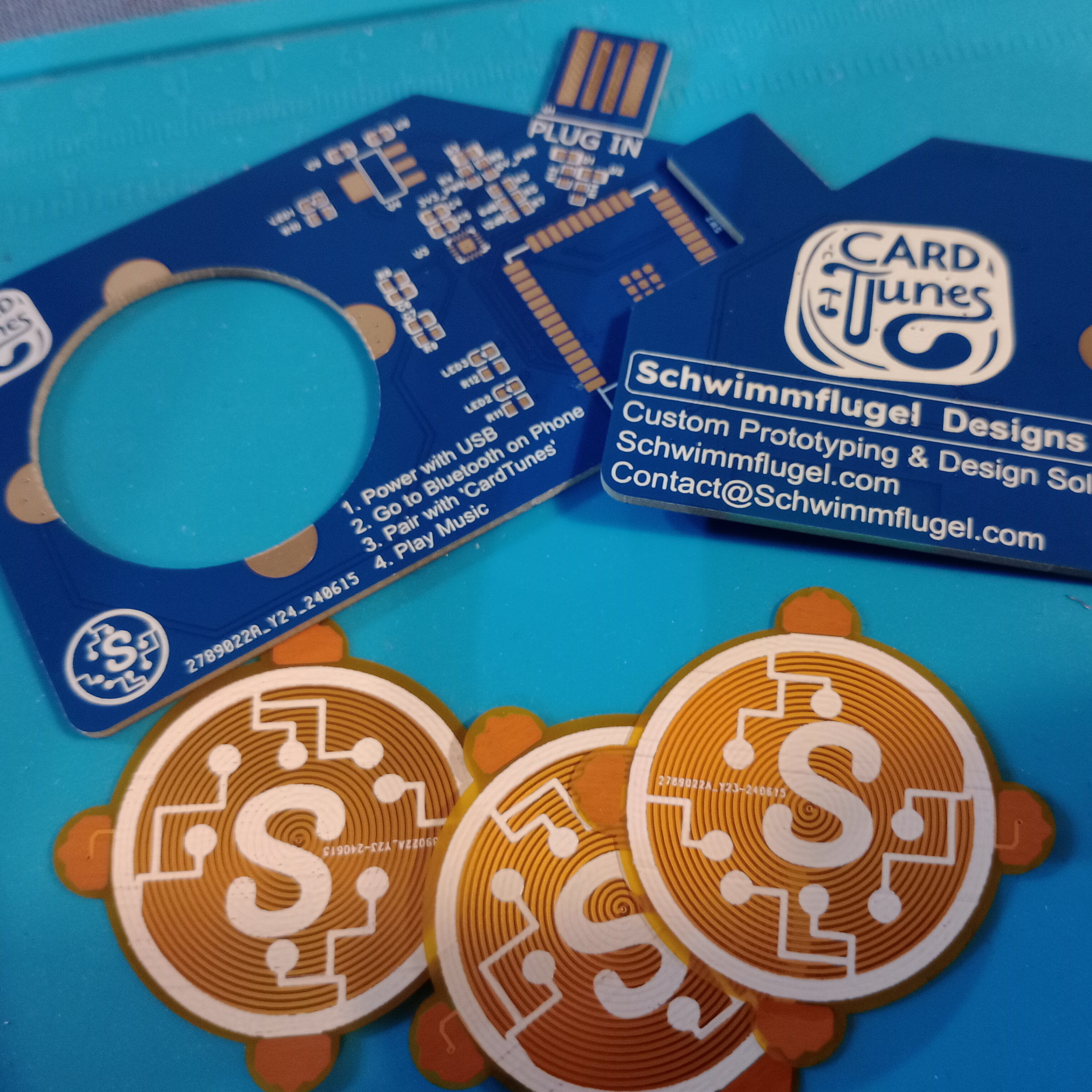
The concept is sound, but in practice, performance was poor. One could identify the song being played, but only if holding the speaker up to one’s ear. The output was improved considerably with the addition of a small permanent magnet behind the card, but of course this compromised the original vision.
Even though the concept of making a speaker from two flexible PCB panel coils had only mixed success, we love seeing this kind of effort and there’s a lot to learn from the results. Not to mention that it’s frankly fantastic to even have a Bluetooth speaker on a business card in the first place.
The 2024 Business Card Challenge is over, but judging by all the incredible entries we received, we’re thinking it probably won’t be too long before we come up with another sized-constrained challenge.
Continue reading “2024 Business Card Challenge: CardTunes Bluetooth Speaker”