How may radios do you own? Forget the AM/FM, GMRS/FRS radios you listen to or communicate with. We’re talking about the multiple radios and antennas in your phone, your TV, your car, your garage door opener, every computing device you own- you get the idea. It’s doubtful that you can accurately count them even in your own home. But what principles of the electromagnetic spectrum allow radio to work, and how do antenna design, modulation, and mixing affect it? [Michał Zalewski] aka [lcamtuf] aims to inform you with his excellent article Radios, how do they work?
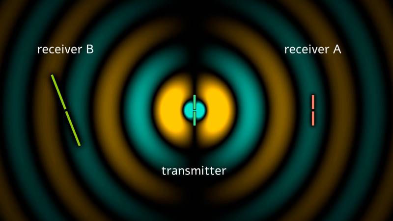
For those of you with a penchant for difficult maths, there’s some good old formulae published in the article that’ll help you understand the physics of radio. For the rest of us, there are a plethora of fantastic illustrations showing some of the less obvious principals, such as why a longer diploe is more directional than a shorter dipole.
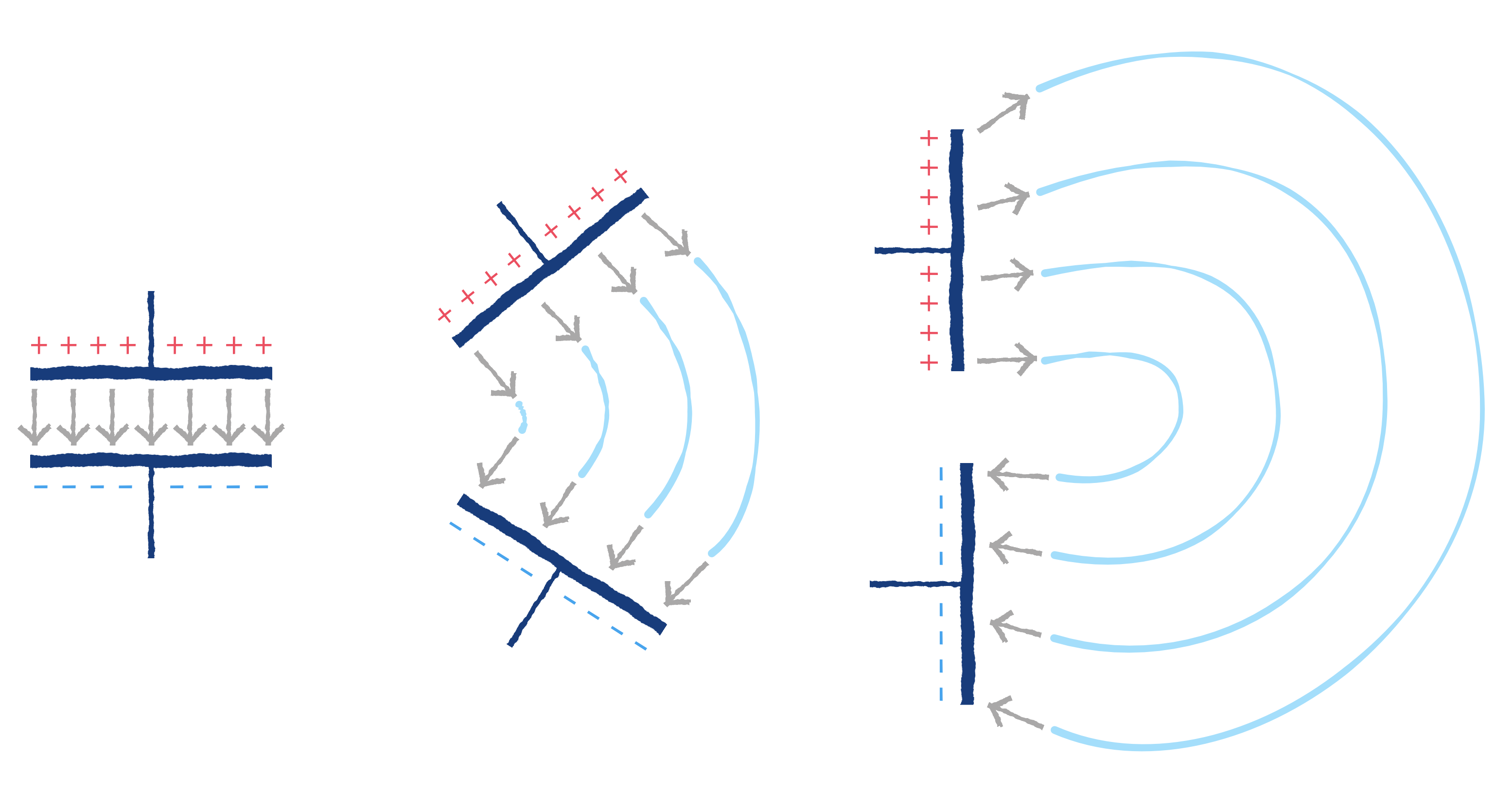
The article opens with a thought experiment, explaining how two dipole antennas are like capacitors, but then also explains how they are different, and why a 1/4 wave dipole saves the day. Of course it doesn’t stop there. [lcamtuf]’s animations show the action of a sine wave on a 1/4 wave dipole, bringing a nearly imaginary concept right into the real world, helping us visualize one of the most basic concepts of radio.
Now that you’re got a basic understanding of how radios work, why not Listen to Jupiter with your own homebrew receiver?


1/4 wave dipole. YMMD. 😃👍
That all we to listen too inmy day it’s different know
I thought that was lacking too. If I remember correctly, in a dipole antenna, when the feed point is in the middle you have current going along the antenna as the charges propagate, and that current makes a magnetic field that changes 90 degrees out of phase with the electric field in a particular orientation, and its this combined magnetic and electric field that creates the “ripple” in the EM field that starts to radiate outwards.
Revisit maxwells equations and run through the curl of E being related to derivated of B and visa versa. You can see the phase difference of a propagating wave in vacuum is zero.
Wonderful article and a good read. However, a common mistake — The plural of antenna, as it applies to RF, is antennas. Antennae is plural for insect sensory organs.
How many boxen do you need to fit all the antennae?
GrammarianADay be dat weigh. ->
It’s an inherent property; information about what charges are doing spreads at the speed of light in all directions, but is averaged out with everything else, and interacts with lots of things to produce transparency, reflection, absorbtion, etc. It only looks like a wave under some conditions but we almost always use those because it’s much easier that way.
If you alternate the status of the field at a constant rate without letting it interact with anything or moving, and then look at how far the information has gotten through empty space as a function of time and distance, then there is a certain distance and a certain time between successive peaks, which is the core point of the c = f * λ aka speed = frequency * wavelength equation. Since it looks like a duck and quacks like a duck, at least when you put it in a pond and throw bread at it, it’s easy enough to call that a wave.
You have to come back and make a new equation if you want to know the distance between observable peaks when propagating inside a transparent material like glass, where the interaction with the charges of the matter combines to produce a result that when expressed as a wave has less distance covered in the same time.
If, like we usually do, you want to separate the analysis of the fundamental force electromagnetism into the electro component and the magnetism component, you can get wave components at right angles to each other and to the propagation direction. Then you can describe matter with permittivity and permeability, and add more variables to your equations so we can continue thinking about waves since we like waves, waves are nice. We can also use that to talk about bending waves and having waves with directional properties (polarization) to get them to make sense with matter that interacts in directional ways like shallow reflections and birefringence and stuff.
Sometimes, like when we’re looking at modulation, we need to account for how we’re not using waves that stay constant forever, but we want to keep using waves. So since the contributions all add up anyway, we can say that a particular sequence of variation is equivalent to the sum of a bunch of different-frequency waves offset in time by a certain amount. And really, it acts that way in all sorts of meaningful ways, so having a spectrum of relevant component waves is a good solution. I’m not sure if there’s an ongoing pedantic argument about whether we’re making more up by doing this or by saying light slows down in glass, but that sounds like a fun way to nerd-snipe.
Trying to get into near and far field stuff using the tools we generally use is annoying, at least for me. We basically define near field based on the approximate distance where a normal analysis is annoying for people whose brains aren’t twisted like a corkscrew. Normally we just say that up really close the thing couples with the receiver and interacts according to a different set of equations, and a bit further than that but not too far things are a bit screwy and you get more interaction than you’d expect but you don’t really couple, and then far enough away everything settles down and pretends to be less of a headache. But it’s really just waiting to surprise you, so watch it from a safe distance.
Hi, Ryan you know anybody at IEEE or MEEI or DARPA? Oh or maybe the NSA!