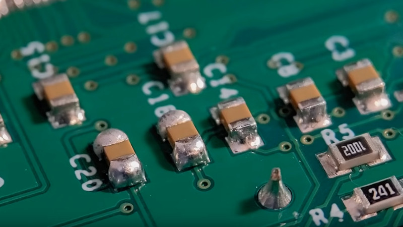
Hand soldering of surface mount components is a bread-and-butter task for anyone working with electronics in 2024. So many devices are simply no longer available in the older through-hole formats, and it’s now normal for even the most homebrew of circuits to use a PCB. But how do you solder your parts? If like us you put a blob of solder on a pad and drop the part into it, then [Mr. SolderFix] has some advice on a way to up your game.
The blob of solder method leaves a little more solder on the part than is optimal, sometimes a bulbous lump of the stuff. Instead, he puts a bit of flux on the pad and then applies a much smaller quantity of solder on the tip of his iron, resulting in a far better joint. As you can see in the video below, the difference is significant. He starts with passives, but then shows us the technique on a crystal, noting that it’s possible to get the solder on the top of these parts if too much is used. Yes, we’ve been there. Watch the whole video, and improve your surface mount soldering technique!
He’s someone we’ve featured before here at Hackaday, most recently in lifting surface mount IC pins.


Mr. Solderfix is awesome, just really simple videos, full of tips, shows you just how simple soldering is. Flux, heat, timing, feed rate…
Gonna sound weird, but whenever I’m teaching someone to solder SMD, I tell them to think of flux as putting a little oil in the frying pan first.
Weird, weird metaphor, I know, I know, but somehow people get it.
I like this. Will be shamelessly stolen. You can’t have it back!
I like this. Will be shamelessly stolen. You can’t have it back
You’re a genius. I like this comparison.
TLDR: Use flux.
What he didn’t mention is to use thin wire solder, it’s hard to dose small amounts with wire diameter over 0.8mm.
And wider diameter solder takes slightly longer to melt, adding a bit more risk od over overheating your parts.
I just use tin paste. Put a blob on the pad, component on top, and press it down with the tip of a needle before touching it with the iron.
When soldering large boards with a great number of components, the solder blob method is still superior. In general, the only reason you would have trouble with excessive solder on the pad with the “apply to one pad” method is if the solder you are using is too large in diameter. The best method is to use fine wire solder, and apply very little to the pad. Stick the components down, then go back through the board, first soldering the unsoldered pins, then adding a small amount to the soldered pins. If you end up with a few pads that have too much solder, simply apply a small amount of flux and suck a bit off with a clean iron tip.
I understand why one might be tempted to use the flux first method, but this method is very messy and time consuming; you also depend on the ideal case of the solder staying on the tip of the iron, which requires very frequent tinning, cleaning, and replacement of the tip. With the one-pad method applied properly, you can do hundreds of 0402 components in an hour with very professional looking joints.
I agree with you 100%
It’s really like some people haven’t read their IPC standards, smh
Instead of moaning, maybe you can share a specific IPC number with the rest of the class.
You can also use solder wick to clean up the blobs, altho it might need a bit of flux, aka this is a faster method prolly
Got .1 mm solder, new tip on a good iron once a week, quality magnification and a very steady hand all yours will look like this. Missing one of these and not.
For clarity, do you change tips weekly? As a hobbyist I’ve yet to change tips in my clone T9x
I am guessing they meant tin. Meaning tin the tip once a week.a new tip a week is a lot unless you are doing ALOT of soldering.
Err. this should have been t35..
Flux the pad, place component, tin iron tip, press iron tip to pad/component, solder flows onto component and pad. Rinse and repeat.
The video is nice and clear and will probably improve solder quality for lots of people. The key here is to eliminate guesswork; you can totally pre-tin a pad and place the component, but most people would be surprised by how little solder is neccessary. It’s also always a compromise between actual solder joint suitability, looks, effort and cleanup effort. To be honest, I usually just go for stencils or hand-apply solder paste using a syringe with fine tip and then use hot air. Not so much for ICs, but small two-pin components are just a bit of a hassle to work with if you want to get nice-looking solder joints.
I want my solder joints to look nice as much as any other guy; however, there are reasons to go for “good enough” instead of “perfect”: excessive rework weakens solder joints by growing the size of the intermetallic. Also, each additional high-temperature heating cycle causes component stresses, which is especially bad for MLCCs. In addition, pads for small components are very delicate and can be lifted off the PCB quite easily if too much heat is applied. Each rework cycle provides opportunity for something to go wrong, so it’s best to avoid it as much as possible. So I’d add that instead of trying to get the perfect solder joint, try to get it reasonably right the first time. For example, in the video, the initial tack solders would probably suffice and not need rework. You can clearly see that he has experience and knows what he’s doing.
Strangely enough, I use an off-cut of solder wick that is already ‘saturated’ with solder to wick off over soldered joints. This has the effect to ‘level’ off solder joints and either add or remove solder from the joint.
Im a 58year old lady whose been working for an electronics company for atleast 25 years… I wish i could also give the younger generations the knowledge i got as now im on the new ipc std as the one i used before is been upgraded…. Im from Soweto Jabulani thank you
All good points, but coulda’ been done in a 45 second video and two Comments.