Playing Chess Against Your Printer, With PostScript

Can you play chess against your printer? The answer will soon be yes, and it’s thanks to [Nicolas Seriot]’s PSChess. It’s a chess engine implemented in PostScript, of all things. It’s entirely working except for one last hurdle, but more on that in a moment.

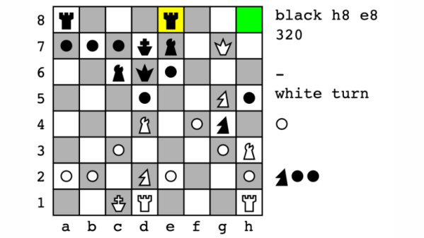
What’s it like to play PSChess? Currently, one uses a PostScript interpreter (such as GhostScript) to run it, much like one would use the Python interpreter to run Python code. The user inputs moves by typing in commands like d2d4 (representing a piece’s source coordinate and a destination coordinate on the 2D board). Then the program makes a move, and outputs an updated board state to both the console and a PDF document. Then it’s the user’s turn again, and so on until somebody loses.

The chess parts are all working, but there’s one last feature in progress. The final step of the project is to enable PSChess to be run directly on a printer instead of using GhostScript as the interpreter. Intrigued? You can find the code at the project’s GitHub repository.

So why PostScript? While it is a Turing-complete stack-based interpreted language, it was never intended to be used directly by humans. There are no meaningful development tools to speak of. Nevertheless, [Nicolas] finds PostScript an appealing tool for programming projects and provides tips and techniques for like-minded folks. One of the appeals is working within constraints to solve a problem, just like implementing a chess engine in only 4k, or draw poker in 10 lines of BASIC.

Using Electroadhesion To Reversibly Adhere Metals And Graphite To Hydrogels And Tissues

The usual way to get biological tissues and materials like gels and metals to stick together is using sutures, adhesives or both. Although this generally works, it’s far from ideal, with adhesives forming a barrier layer between tissues and the hard or impossible to undo nature of these methods. A viable alternative might be electroadhesion using cation and anion pairs, which uses low-voltage DC to firmly attach the two sides, with polarity reversal loosening the connection with no permanent effects. This is what a group of researchers have been investigating for a few years now, with the most recent paper on the topic called Reversibly Sticking Metals and Graphite to Hydrogels and Tissues by [Wenhao Xu] and colleagues published this year in ACS Central Science.

This follows on the 2021 study published in Nature Communications by [Leah K. Borden] and colleagues titled Reversible electroadhesion of hydrogels to animal tissues for suture-less repair of cuts or tears. In this study a cationic hydrogel (quaternized dimethyl aminoethyl methacrylate, QDM) was reversibly bonded to bovine aorta and other tissues, with said tissues functioning as the anionic element. Despite demonstrated functionality, the exact mechanism which made the application of 3-10 VDC (80 – 125 mA) for under a minute (10+ seconds) cause both sides to bond so tightly, and reversibly, is still unknown. This is where the recent study provides a mechanism and expands the applications.

Continue reading “Using Electroadhesion To Reversibly Adhere Metals And Graphite To Hydrogels And Tissues”

A Single Transistor Solid State Tesla Coil

Tesla coils are one of those builds that capture the interest of almost anybody passing by. For the naïve constructor, they look simple enough, but they can be finicky beasts—beasts that can bite if not treated with respect. [Mirko Pavleski] has some experience with them and shares it with us over on Hackaday.io. One of the first big improvements of this build style is the shift from the originally used spark gap commutator to that of a direct AC drive via a MOSFET oscillator. This improves the primary drive power for its size and eliminates that noisy spark gap. That’s one less source of broadband RF noise and the audible racket these produce.

A hand holding a secondary coil for a Tesla coil build
You can buy ready-wound secondary coils from the usual CN suppliers

The primary side of a Tesla coil is usually a handful of turns of thick wire to handle the current without melting. This build runs at two or three amps, giving a primary power of around 150 Watts. However, this is quite a small unit; with larger ones, the power is much higher, and the resulting discharge sparks much longer. On the secondary side, the air-coupled coil is formed from 520 turns of much thinner wire since it doesn’t need to convey so much current. That’s the thing with transformers with large turns ratios — the secondary voltage will be much higher, and the current will be correspondingly much lower. The idea with Tesla coils is that the secondary circuit forms a resonant circuit with the ‘top load’, usually some hollow metal can. This forms an LC circuit with a corresponding resonant frequency dependent on the secondary inductance values, the object’s capacitance and anything else connected. The primary circuit is designed to resonate at this same frequency to give maximum power coupling across the air gap. Changing either circuit can spoil this balance unless there is a feedback circuit to keep it in check. This could be with a sense coil, a local antenna or something more direct, like in this case.

To ensure the primary circuit doesn’t melt, it needs to be able to drive a reasonable current at this frequency, often in the low MHz range. This leads to a common difficulty: ensuring the switching transistor and rectifying diode are fast enough at the required current level with enough margin. [Mirko] points out several components that can achieve the operating frequency of around 1.7 MHz, which his top load configuration indicates.

For a bit more info on building these fascinating devices, you could check out our earlier coverage, like this useful guide. Of course, simple can be best. How about a design with just three components?

Continue reading “A Single Transistor Solid State Tesla Coil”

A Practical Guide To Understanding How Radios Work

How may radios do you own? Forget the AM/FM, GMRS/FRS radios you listen to or communicate with. We’re talking about the multiple radios and antennas in your phone, your TV, your car, your garage door opener, every computing device you own- you get the idea. It’s doubtful that you can accurately count them even in your own home. But what principles of the electromagnetic spectrum allow radio to work, and how do antenna design, modulation, and mixing affect it? [Michał Zalewski] aka [lcamtuf] aims to inform you with his excellent article Radios, how do they work?

A simple illustration compares a capacitor to a dipole antenna.

For those of you with a penchant for difficult maths, there’s some good old formulae published in the article that’ll help you understand the physics of radio. For the rest of us, there are a plethora of fantastic illustrations showing some of the less obvious principals, such as why a longer diploe is more directional than a shorter dipole.

The article opens with a thought experiment, explaining how two dipole antennas are like capacitors, but then also explains how they are different, and why a 1/4 wave dipole saves the day. Of course it doesn’t stop there. [lcamtuf]’s animations show the action of a sine wave on a 1/4 wave dipole, bringing a nearly imaginary concept right into the real world, helping us visualize one of the most basic concepts of radio.

Now that you’re got a basic understanding of how radios work, why not Listen to Jupiter with your own homebrew receiver?

SMD Soldering, Without The Blobs

Hand soldering of surface mount components is a bread-and-butter task for anyone working with electronics in 2024. So many devices are simply no longer available in the older through-hole formats, and it’s now normal for even the most homebrew of circuits to use a PCB. But how do you solder your parts? If like us you put a blob of solder on a pad and drop the part into it, then [Mr. SolderFix] has some advice on a way to up your game.

The blob of solder method leaves a little more solder on the part than is optimal, sometimes a bulbous lump of the stuff. Instead, he puts a bit of flux on the pad and then applies a much smaller quantity of solder on the tip of his iron, resulting in a far better joint. As you can see in the video below, the difference is significant. He starts with passives, but then shows us the technique on a crystal, noting that it’s possible to get the solder on the top of these parts if too much is used. Yes, we’ve been there. Watch the whole video, and improve your surface mount soldering technique!

He’s someone we’ve featured before here at Hackaday, most recently in lifting surface mount IC pins.

Continue reading “SMD Soldering, Without The Blobs”

Too Much Over-optimization Is Never Enough!

A discussion came up on the Hackaday Discord PCB design channel about resistor networks, and it got me thinking about whether we (the hacker community) use them in designs or not. These handy devices often take the shape of an IC, SMD or otherwise, but between the pins are a bunch of resistors instead of active silicon. They come in all sorts of configurations and tolerances, but the point is usually the same: When you need a bunch of similar resistors, it’s cheaper to go with a network package.

But how much cheaper? I did a quick search for 1 kΩ resistors and the corresponding network, and came up with similar prices for the resistors and networks – but the network has eight resistors in it! That’s an eightfold savings! Which, at a price of roughly one cent per piece, is less than a dime. While it’s certainly true that if you’re making a million widgets, saving a penny per widget matters. But do you spend the time to optimize your projects down to such margins? I want to say “of course not!” but maybe you do?

For me, worrying about seven cents in a PCB design that I may make ten of is foolishness. But still, I’ve used resistor networks for their other side effects: the resistors in a common package tend to be very tightly matched, even if their overall tolerance isn’t. If you’re making something like an R-2R DAC, that’s a definite advantage. Or if you’re space constrained, or just hate placing lots of tiny resistors, the networks shine.

I often forget about resistor networks, and when I do think of them, I think of them in terms of cost savings in industrial applications. But maybe that’s not fair – maybe they do have their hacker uses as well. Are there other parts like this that we should all know about?

How Much Bandwidth Does CW Really Occupy?

Amateur radio license exams typically have a question about the bandwidths taken up by various modulation types. The concept behind the question is pretty obvious — as guardians of the spectrum, operators really should know how much space each emission type occupies. As a result, the budding ham is left knowing that continuous wave (CW) signals take up a mere 150 Hertz of precious bandwidth.

But is that really the case? And what does the bandwidth of a CW signal even mean, anyway? To understand that, we turn to [Alan (W2AEW)] and his in-depth look at CW bandwidth. But first, one needs to see that CW signals are a bit special. To send Morse code, the transmitter is not generating a tone for the dits and dahs and modulating a carrier wave, rather, the “naked” carrier is just being turned on and off by the operator using the transmitter’s keyer. The audio tone you hear results from mixing the carrier wave with the output of a separate oscillator in the receiver to create a beat frequency in the audio range.

That seems to suggest that CW signals occupy zero bandwidth since no information is modulated onto the carrier. But as [Alan] explains, the action of keying the transmitter imposes a low-frequency square wave on the carrier, so the occupied bandwidth of the signal depends on how fast the operator is sending, as well as the RF rise and fall time. His demonstration starts with a signal generator modulating a 14 MHz RF signal with a simple square wave at a 50% duty cycle. By controlling the keying frequency, he mimics different code speeds from 15 to 40 words per minute, and his fancy scope measures the occupied bandwidth at each speed. He’s also able to change the rise and fall time of the square wave, which turns out to have a huge effect on bandwidth; the faster the rise-fall, the larger the bandwidth.

It’s a surprising result given the stock “150 Hertz” answer on the license exam; in fact, none of the scenarios [Allen] tested came close to that canonical figure. It’s another great example of the subtle but important details of radio that [Alan] specializes in explaining.

Continue reading “How Much Bandwidth Does CW Really Occupy?”