Amateur radio license exams typically have a question about the bandwidths taken up by various modulation types. The concept behind the question is pretty obvious — as guardians of the spectrum, operators really should know how much space each emission type occupies. As a result, the budding ham is left knowing that continuous wave (CW) signals take up a mere 150 Hertz of precious bandwidth.
But is that really the case? And what does the bandwidth of a CW signal even mean, anyway? To understand that, we turn to [Alan (W2AEW)] and his in-depth look at CW bandwidth. But first, one needs to see that CW signals are a bit special. To send Morse code, the transmitter is not generating a tone for the dits and dahs and modulating a carrier wave, rather, the “naked” carrier is just being turned on and off by the operator using the transmitter’s keyer. The audio tone you hear results from mixing the carrier wave with the output of a separate oscillator in the receiver to create a beat frequency in the audio range.
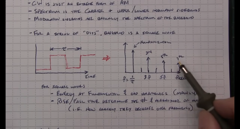
That seems to suggest that CW signals occupy zero bandwidth since no information is modulated onto the carrier. But as [Alan] explains, the action of keying the transmitter imposes a low-frequency square wave on the carrier, so the occupied bandwidth of the signal depends on how fast the operator is sending, as well as the RF rise and fall time. His demonstration starts with a signal generator modulating a 14 MHz RF signal with a simple square wave at a 50% duty cycle. By controlling the keying frequency, he mimics different code speeds from 15 to 40 words per minute, and his fancy scope measures the occupied bandwidth at each speed. He’s also able to change the rise and fall time of the square wave, which turns out to have a huge effect on bandwidth; the faster the rise-fall, the larger the bandwidth.
It’s a surprising result given the stock “150 Hertz” answer on the license exam; in fact, none of the scenarios [Allen] tested came close to that canonical figure. It’s another great example of the subtle but important details of radio that [Alan] specializes in explaining.


the picture looks like the bloke has a probe biro. i now want a probe biro.
Oh wow that would be a great idea
I knew those busted probes I’ve stubbornly hung onto for years would come in handy one day!
I have a narrow bandwidth audio filter for CW reception with a bandwidth probably well under 100hz. Slow CW is fine, but fast CW ‘fuzzes up’. There is no free lunch.
I appreciate this video and was also left thinking about its implications on cw recieve filtering. I have an optional 250Hz filter, but have found I enjoy the sound of the 500Hz in most cases. Perhaps my ears appreciate the more complete ~385Hz reception – pls realize this in an opinion from someone whose decode skills require aggressive reduction of any distractions. Thank you!
Wasn’t ~800 c/s the “ideal” tone frequency, though?
Because human hearing is most sensitive here. Or so I heard.
The bandwidth is unrelated to the beat frequency tone, which is generated in the receiver. What Steven is talking about is the RF bandwidth of the receiver. Limiting the receiver bandwidth (or the transmitter bandwidth) results in less crisp starts and stops of that 800 Hz tone, which makes recognizing characters more difficult.
I don’t think the rise & fall time had to be as fast as he was showing though, and there’s no need to start or end the rise or fall so suddenly, ie, with a sharp corner. For receive, when I was active in CW, I could use a filter than dramatically attenuated a signal even 150Hz away. It didn’t have any trouble with ringing, because unlike the filters on the market, I made it to have a floor, meaning that even though it was really sharp, nothing got attenuated more than 30dB or 60dB (I don’t remember which), regardless of frequency. I wish I could attach a diagram here. Transmitters with a fast rise and fall time would still be audible a fair distance away in frequency, where I’d hear just the clicks. I had three selectable center frequencies, because I was running a direct-conversion receiver, meaning that if I were listening at 800Hz and there were someone 1600Hz away, ie, the same distance on the other side of the beat frequency, they’d sound like they were on top of each other. Being able to change the center frequency of the filter allowed separating them so the unwanted signal was way down.
Someone discovered the Fourier transform of a square wave.
Yep, anyone who really understands signal theory and principles would not be surprised at all by this.
Yeah. But it takes a lot of experience or studying to understand it. You can’t expect that people have a natural understanding of it.
This is a great way to experience it, and to learn it. Try to remember how you learned about this.
I learned this because I put a lot of time into practical experiments and theory in form of videos and text. And I still learn things about this.
I was taught how a square wave is the sum of harmonics in school, years before going to university. That included the sharpness of the edges and Gibbs phenomenon.. Pure maths is a pleasing subject (as is applied maths).The
This is just the same, frequency translated up to the RF carrier frequency. That’s first year undergrad electronics.
In HS you learn it as a ‘fun math fact’.
But it’s like statistics before calculus. Just memorized stuff, pretty pictures.
Fourier was 3rd semester calc IIRC. So freshman year, second half.
Next semester you get to see that there is no such thing as a square wave…Unless you were the kind of EE student that owned an old oscilloscope, then you already knew.
TFA is much better than average for this dump.
The answer actually is that CW uses nearly infinite bandwidth. It’s a square wave.
The bandwidth 60db down isn’t that big though.
Worst station at Field Day is always the CW station with it’s keying harmonics.
There are now initiatives to reduce the key harmonics and there’s a lot of magic that can be done with digital control
If you are doing it correctly, you put some work into making sure the CW waveform is NOT a sharp-edged squarewave specifically to avoid a lot of harmonics.
Books written before I was born talk about CW shaping in tube equipment. It is not a new thing.
What would it look like with even longer rise-and-fall times? What shape and duration of the rise- and fall-time curves gives the narrowest bandwidth for a given words-per-minute?
The bandwidth of OOK modulation (which is what ham radio operators call “CW”, which is insane) *purely* comes from the modulation – it’s just the modulation waveform mixed with the carrier. So what you’re asking is “how is the bandwidth of a square wave related to its rise time” – and there isn’t a pure answer for that, because it depends on how fast the frequency components are falling off.
There’s a ‘rule of thumb’ (BW = 0.35/(risetime in ns)) which is related to the response of a single-pole filter, but obviously filters can be sharper than that.
Don’t all digital signals take infinite bandwidth in a pure mathematical sense? But practically because they are digital (quantized) signals, upon reception we can discount those errors introduced by band limiting. So the bandwidth in such cases is the theoretical minimum needed to successfully infer the original digital signal from the distorted reception. Below limit you have unresolvable ambiguities.
How do we define “digital” here? As two states? On/off? If so, isn’t that more specifically binary, rather?
“Digital” originates from Latin digitus, finger. So a digital signal is a fingered signal, meaning it’s being filtered like with a comb (a comb has fingers).
It’s not being limited to two states only, though.
A “digital” computer system using positive, negative and zero voltage could be technical lydesigned, too.
And it would be digital, but not binary.
So “digital” is about pre-defined states, that are being filtered through a given raster (the comb).
TTL signals are digital, because they have a defined maxmium/minimum range for their logical high/low states.
But does this also apply to morse telegraphy?
I heard that the dot/dash ratio for radio telegraphy is technically being defined in its relative lenght/duration.
But that’s part of the “protocol”, maybe, rather than the nature of the radio signal on an electromagnetic level?
The maxima/minima levels of an CW signal aren’t being defined in an official ISO, DIN or ITU specification, I suppose?
I’m just wondering, because people often throw “digital” into the pod when they really just mean simple binary (two states, power of two, on/off keying).
Speaking under correction. Vy73s.
Your reasoning about what is ‘digital’ is correct. I respond in the negative to your question about protocol somehow changing changing things for CW. The analysis is the same regardless of encoding scheme.
CS is just a special case of AM. It’s AM with a rectangular modulation envelope. Band limiting means that we will not receive the originally sent super-crisp rectangles, we will get some bendy edges, but we can make do and still infer the original signal.
It might be fun to discuss this from the opposite side: if CW is simply detecting a tone, or not detecting a tone, then can it work with /zero/ bandwidth, only centered on the known tone?
The answer of course is ‘no’. But why not?
73 to you Joshua; ag5th
because turning the tone on and off requires frequencies besides the carrier frequency. However, you’ve undoubtedly heard of signals from spacecraft that are out at Jupiter, Saturn, or beyond, that are so week that transmission speeds must be severely limited so that extremely sharp filters can be used at the receiving end (on earth) to shut out the noise that’s only a few Hz away (or a few tens of Hz? I don’t know how sharp they have to go), noise that would otherwise swamp out the desired signal.
Nope. In the mathematical sense, digital signals take exactly one-half their signal rate in bandwidth – thanks, Dr. Nyquist!
But, of course, that’s a noise-free channel: once you try to push it over a physical channel with noise, then you need to know what the target SNR is, which, in the simple case of Gaussian noise, gets you the Shannon-Hartley theorem.
I think you get precisely my point. And perhaps I stated it poorly.
There is no ‘digital’.
It’s all just a bunch of simplifying engineering squints. Be aware of assumptions and limits.
Avoid ‘pure mathematicians’. You’ll get cooties. Divide by 0!
In before ‘aktually, quanta!’ Physicists carry multidrug resistant cooties.
I think you get it.
I cannot parse your last sentence.
Someone will be along to say: ‘There is no analog, all energy is quantized.’
brilliant. we are all digital in the end.
Not all quanta are the same size.
Velocity and distance are part of it though, and they are most definitely analog.
For 24 wpm the maximum fundamental is 10 Hz. The rise & fall times determine how many harmonics are generated. The conventional rule is 0.35/Tr. Tr = Tf = the -3 dB point in the harmonic decay.
6 ms Tr is ~58 Hz.
Double that for straight OOK modulation, because you generate both positive and negative harmonics around a carrier.
I would challenge ANYBODY to copy code sent at the minimum possible rise and fall times for the speed they’re sending. Dits turn into mush, and dahs aren’t much nicer.
As long as the channel is non-fading and the SNR is high enough, use threshold detection for the presence or absence of signal. Then regenerate the audio tone with faster edges.
I assume there are sophisticated mathematical techniques that would be even better; deconvolve the rise/fall function.
If you look at the tests on QST, they always show a “ramping” envelope for CW.
I attend ended broadcast engineer’s school in the 70’s
Our instructor showed through math and experiment that there was indeed “bandwidth” from CW.
Just because math shows something, does not prove it exists …BTW. Just look at how scientists have added variables to well worn formulas and theories, in order to make their math add up to better experiments experiments…
1. We students proposed a thought experiment where we would have a transmitter in an absorptive box, and open and close a shutter with near instant speed.
2. We also proposed a “fast switch” (super fast) that would stay off until the signal from the transmitter stabilized.
We thought that IF our transmitters were perfect, there would be no bandwidth.
(Let’s skip the “no information” arguments for now.)
What do readers think of #1 and #2 ? (70 and still learning.)
Theory, math and measurements all show that Morse transmissions DO have a non-zero BW, regardless of ideas like zero crossing switching, ideal stability of the transmitter, etc. because it is a form of Amplitude Modulation. Any signal that changes quickly in the time domain, results in high frequency context in the frequency domain.
Sometimes it’s more like just because the math says the universe works a certain way behind the scenes doesn’t mean it will actually appear that way when you observe it the normal way. There might be little correction factors we throw in sometimes that turn out not to be fundamental, but it doesn’t mean the equation without them is fundamental either – it must be missing something. I think in this case it’s easiest to say that waves that go on forever are a convenient tool we can get pretty close to, but beginning or ending one is incompatible with the idea of an infinite constant wave.
Changing one slowly, we know how to handle; it to all intents and purposes is the same as adding up multiple component waves, and if you did have the same separate components, you could put them back together and observe the same thing, because EM does fundamentally add. In that method of looking at the EM field, changing a wave arbitrarily fast continues to be possible, and takes more and more bandwidth the faster you go, even if you try to be clever and start it at a certain phase of the wave.
A lot of times you go to switch a wave on and off, like flipping a switch feeding a motor or a transformer, and then you notice that even though the voltage is zero at some point, that doesn’t mean there isn’t a 60hz wave you can use to describe what’s going on at that moment – actually the voltage is changing very fast right there. So looking at things with the complex impedance model, the model says the big inductors will have something to say about that fast voltage change – they will probably say that you’re going to have a big inrush current.
Read about Coherent CW (CCW) on amateur radio here: https://www.sigidwiki.com/wiki/Coherent_CW
Waaay back when, I remember seeing keying ciruits for CW transmitters, that limited the rise and fall rates of the transmitter, specifically to control the bandwidth of the transmitter, and to reduce what they called “splash” that showed up all across the band. Most homebrew circuits I see today don’t bother with this, because for a CW only transmitter, you have to be able to shape the square wave coming from the key into a kinder waveform, and then apply that to a linear modulator, which is almost as much trouble as SSB.
RC circuits are tricky.
The trapezoidal envelopes used in the signal generator in the demonstration are unrealistic, unless you’re actually modulating your transmitter with a trapezoid wave, which nobody does. A more realistic waveform would be a square wave passed through a low-pass LC filter, which in addition to limiting the slew rate in the middle part of the rising edge, also rounds the corners off, and it’s those corners that contribute a significant portion of the spectrum of the waveform. As you can see in [Alan]’s final example, which is the RF coming out of his Elecraft transmitter, those corners in real life ARE rounded off, at least in the case of well-designed transmitters. And the spectrum display clearly shows that this is not nearly as dirty as the simulated signal using a trapezoidal envelope.
Absolutely right.
Yes; I tried to express that earlier, but you did it better.
How much bandwidth does cw need, technically a few hertz and some gap for isolation
Cw is literally just switching the carrier on or off, doesn’t need “bandwidth” unless you transmit a constant carrier and modulate a tone on it like a voice instead of a bfo circuit
Morse code transmissions ARE a form of Amplitude Modulation – thus it DOES occupy a measurable bandwidth.
Bandwidth is all of the frequency content in the modulating times 2. You can’t modulate a carrier without increasing the bandwidth.
This includes harmonic content in the modulating signal. Which is why, when properly done, the CW attack/release times are not instantaneous, but are bandwidth limited. This has been done since tube days. I used to live in the Phoenix library system, I read every year of the ARRL handbook they had, and all issues of CQ, QST, etc. that I could get my hands on. Work went into waveshaping the CW modulation to prevent splatter, which is one name for excess bandwidth caused by fast switching.
I presume you are using a digital Mixed Signal Oscilloscope (MSO) in Fast Fourier Transform (FFT) mode for the Occupied Band-Width (OBW) measurements. However you did not specify what Window Function [1] you used, and why. As measuring Carrier to Noise is important, perhaps a Blackman–Harris or Flat Top window with low sidelobes would be a good choice?
1. Window Function
https://en.wikipedia.org/wiki/Window_function
It was a Blackman Harris window, computing the spectrum using a Chirp-Z transform from the baseband I/Q data coming from an integrated DDC (digital down-converter) in the scope.
How should I think about this wrt to CW. The key is up (nothing transmitted) then the operator sends a dit. The dit is a key down, hold closed for a brief time and then let the key up. There is nothing (hopefully) coming out of the transmitter when the key is up Q: what does the spectral model say is happening when the key is up? My confusion: no RF should be coming out of the transmitter when the key is up but the spectral model says there will be harmonics signals present. Does that mean I will hear signals at harmonic frequencies even with nothing being transmitted. What is the spectral display telling me? I’m sure this is a beginner question so can someone help me?