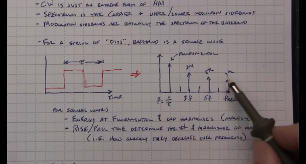
For a long time, a Morse code proficiency was required to obtain an amateur radio license in many jurisdictions around the world, which was a much higher bar of entry than most new hams have to pass. Morse, or continuous wave (CW) is a difficult skill to master, and since the requirement has been dropped from most licensing requirements few radio operators pick up this skill anymore. But if you like a challenge, and Morse itself isn’t hard enough for you, you might want to try out this extremely small Morse paddle.
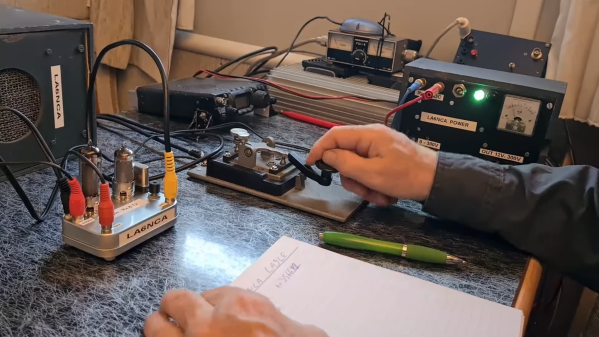
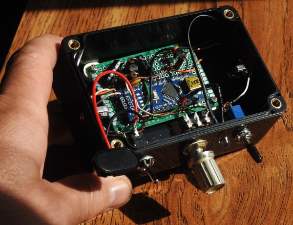
Originally meant for portable operation, where hiking to something like a mountain top with radio gear demands small, lightweight, and low-power options, this paddle is actually not too complex. It attaches to most radios with a 3.5 mm stereo cable and only has two paddles on flexible metal arms which, when pressed against the center of the device, tell the radio to either produce continuous “dits” or “dahs”. For portable use the key sits inside a tiny plastic case and only needs to be pulled out and flipped around to get started. And, while not waterproof, [N6ARA] reports that it’s so small you likely could just shield it from the rain with your other hand if you needed to.
Presumably, this paddle actually wouldn’t be that much different than using any other paddle except for the fact that it’s not heavy enough to resist the force of use, so you’d have to hold it with your other hand anyway. And, while this is a product available for purchase it’s simple enough that, presumably, the design could easily be duplicated with just a few parts. Paddles like this were made as an improvement to older technology like straight keys which require the operator to produce the correct lengths of tones for each character manually. While you can get higher speeds with a paddle, there are still some dedicated CW operators using a straight key.