Perhaps the simplest way to regulate a DC voltage is using a voltage divider and/or an active device like a Zener diode. Besides simplicity, they have the additional advantage of not being particularly noisy, but with a major caveat: they are terribly inefficient. To solve this problem a switching regulator can be used instead, but that generally increases complexity and noise. With careful design, though, a switching regulator can be constructed to almost completely replicate a linear regulator like this drop-in TO3 replacement. (Google Translate from German)
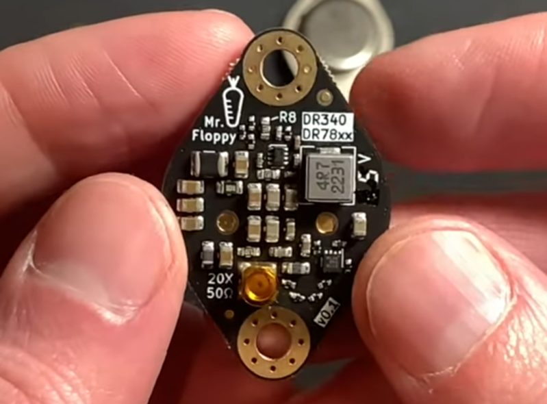
While the replacement regulator was built by [Mr. Floppy], the units are being put to the test in the linked video below by [root42]. The major problem these solve compared to other switching regulators is the suppression of ripple, which is a high-frequency artifact that appears on the DC voltage. Reducing ripple in this situation involved designing low-inductance circuit traces on the PCB as well as implementing a number of EMI filters on both input and output. The final result is an efficient voltage supply for retrocomputers which has a ripple lower than their oscilloscopes can measure without special tools.
[root42] is not only testing these, but the linked video also has him using the modules to repair a Commodore 1541 which originally had the linear TO3 voltage regulators. It’s definitely a non-trivial task to build a switching power supply that meets the requirements of sensitive electronics like these. Switch mode power supplies aren’t new ideas, either, and surprisingly pre-date the first commercially-available transistor although modern ones like these are much less expensive to build.


> Since the ripple voltages are so small, there is an RF connector (MMCX) on the PCB, which serves as a test point for V OUT . This would allow you to measure the voltage very precisely without external interference.
Now that’s showing off. Impressive work
I don’t think it has anything to do with that. More so because it’s simply an easy way to test that the device is in specs – thus catching when the Chinese manufacturer starts substituting substandard or wrong parts.
A linear regulator can have a noise figure of 30 micro-Volts RMS over a 100 kHz bandwidth. That would be difficult to measure on an oscilloscope. If the guy is measuring 30 milli-Volts, either the regulator is horribly noisy, or he’s just measuring ambient noise.
To give a bit of context and comparison, if you have 30 mV of noise over 5 Volts, that’s enough to be picked up by your Arduino Uno’s ADC and throw off your measurements.
0.030 V / 5 V = 0.006
2^10 * 0.006 = 6.144 the amount of ripple you’d see in the ADC output at 10 bits.
2^2.6 = 6.06 equivalent number of bits
In other words, you lose approximately 2.6 bits of resolution out of 10 bits just due to this added noise, because the Arduino is using its VCC as the voltage reference. This is why they use a linear regulator on the board. The datasheets I can find don’t list the noise figures, only the power supply noise rejection ratios, but it doesn’t need to be anything stellar to beat a switching regulator.
There’s also an added twist with switching regulators: the noise is concentrated on a particular frequency and its harmonics, but you don’t know what those are.
Why? Because the perennial problem of switching regulators is high quiescent current demand to keep the switching going on. Their efficiency goes way down at partial load, which is remedied by adjusting frequency according to load and by pulse-skipping techniques, which throw the ripple all over the spectrum and creates spurious peaks. If you want high efficiency and wide power band, you get dirty power.
Hence why, for applications where you don’t want to deal with the noise, a hybrid approach is used where the switching mode regulator is combined with a linear regulator in line.
Which is why it is nearly always a bad idea to use the +5 supply for the ADC’s Vref. Set the Arduino to use its internal buried junction reference instead:
analogReference(INTERNAL); // set ADC reference to internal 1.1V
analogRead (A1); // dummy read needed to initialize reference to internal
and you can do even better by measuring the Vref of your particular Arduino and using that value for your calculations.
And you get a + or – 10% error on your readings for free!
(check the datasheet, it is really 10%!)
But then you can’t directly measure to 5 Volts.
There are other things like supersampling that can restore the lost precision, and it’s a good idea anyways if you’re not in a hurry, but still you don’t want that extra noise.
Wow, this is really getting OT … root42 said that Mr. Flopy made this circuit to be able to replace the old regulators of heated-up microcomputers, which additionally run on higher input voltage since Europe switched mains power from 220V to 230V in the 1990s, and thus heat the device up even more. And to replace older drop-in designs that have like 200mv ripple voltage! Additionally it offers short-circuit protection and is still cheaper than buying a fake LM78xxK from a far-east chip scraper.
It’s not made for absolutely exact ADC readings and Arduino designs don’t use TO-3 linear regualtors ;) It’s just made for stressing you old computing/entertainment machines less than other options.
The HF connector exists because a hobbyist’s scope probe (esp. via the ground clamp) would pick up more residual noise than the noise generated by this circuit. Which you can see when root42 struggles to “catch up” with the actual noise reading supplied in the datasheet.
If your measurements are that critical, you should be using the internal reference with a bypass cap or an external reference, not Vcc.
https://www.digikey.com/en/articles/understanding-linear-regulator-noise-in-hybrid-power-supplies
That’s what I was thinking, these things would turn a clean quiet Astron power supply in to a noise problem,
I’ve had really good luck with the kinds from EZSBC in particular, but I know there are many other varieties out there to choose from which is awesome. Great way to reduce heat output on a Commodore 1541 drive or Rev E VIC-20 motherboard.
Maybe I missed it; has anyone found a link to purchase these?
Thanks for posting. So far, the only way is to contact Mr. Floppy directly via email or on the DOSreloaded forum, which is mentioned above in the link. There is also a datasheet linked. We will post the design data soon, as we classified it as Open Source Hardware. We just wanted to collect some real life feedback from first users.
Thank you for that info Mr Floppy, I’ll keep my eye out for the official release. Extremely nice work!
Umm, ezsbc.com?
Thank you very much!
No, EZSBC is absoultely not related. Not even on the same continent afaik.
Mr. Floppy’s layout seems quite refined and the circuit is much more complex, because it has overload/short protection and to produces a lot less noise than EZSBC’s products.
I was just thinking of those in old 1541s, the big one with the internal transformer. The later 1541-II has external power supply and doesn’t get warm at all
Are there other voltages available, outside of those listed? 24v, negative versions of 5 and 12?
According to the datasheet, you can configure it to any positive voltage between 3.3V and 15V (or a little more like 18V) using a single resistor, wich can be determined by a simple formula. A few values are given but you may make up your own.
Setting it to 24V could work, but hasn’t been tested – it was relatively unusual in microelectronics, which this regulator was made for.
A negative version would need to be a different layout, but I guess it’s coming. However most micro applications don’t put much load on negative rails (like for attenuation voltage, audio opamps or RS232) so they’re using a TO220 or even smaller linear regulator, which also isn’t prone to heat up your application so much that you want to get rid of it ;)
Would love to see this drop in for a 7924 or a 7824CV. At 24V and 1.5A, we could contemplate retrofitting a metal TO3 bottle cap housing. Get the looks and heat dissipation.
Voltage dividers don’t regulate voltage.
And very inefficient to use divider for power source, you’re dumping a lot of heat through the resistors. I’d sooner use emitter-follower design (power in to collector, zener diode at v_out + 0.7v from collector to base, resistor from base to ground, and emitter is power out) than to use voltage divider
Correction: resistor from collector to base and zener diode from base to ground
Perhaps a sketch or diagram?
He’s talking about a BJT voltage follower, where the base of a transistor is connected to some sort of voltage reference and the transistor passes current from a higher voltage supply through the collector to the emitter, which is connected through a resistor to ground.
When current flows through the resistor, the voltage at the emitter rises up by Ohm’s law until there’s barely any difference to the voltage reference at the base, at which point the transistor starts to shut off, limiting the current through the resistor, so regulating the voltage at the emitter to a bit less than the reference input at the base.
It’s not a good voltage regulator because of how the setup works. If you draw current to a load past the resistor, the voltage sags down, because it has to for the transistor to open up and let more current through. The voltage can be anything from a few millivolts up to a Volt under the reference, depending on the parts, the reference, and the load.
This circuit is actually and more typically used to buffer signals as current amplifier rather than a voltage regulator. The voltage at the emitter follows the input 1:1 minus a bit which usually doesn’t matter, but the current is amplified by 50-500 times, which can then drive other circuitry without loading up the input signal too much. Something like a microphone pre-amp.
Given how much more complicated it is, this is clearly a disintegrated circuit.
Great for TTL logic, but analog circuits like radios and audio still need linear power supplies.
Beautiful work, thanks for sharing.