It was probably a reasonable assumption that the “Tiny” in our recently concluded Tiny Games Contest mostly referred to the physical footprint of the game. And indeed, that’s the way most of the entries broke, which resulted in some pretty amazing efforts. [Anders Nielsen], however, took the challenge another way and managed to stuff a seagull-centric side-scroller into just 500 bytes of code.
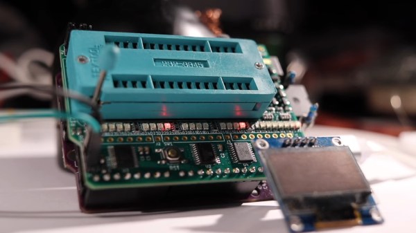
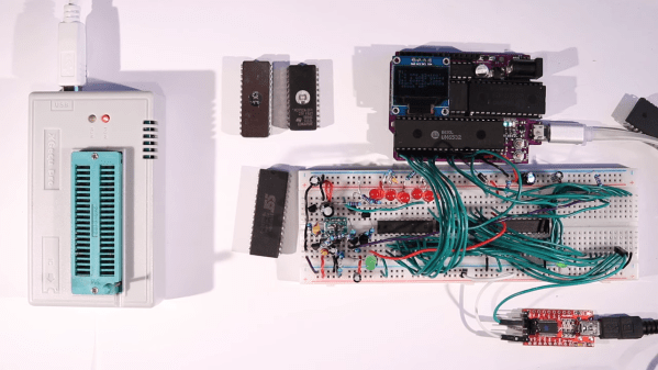
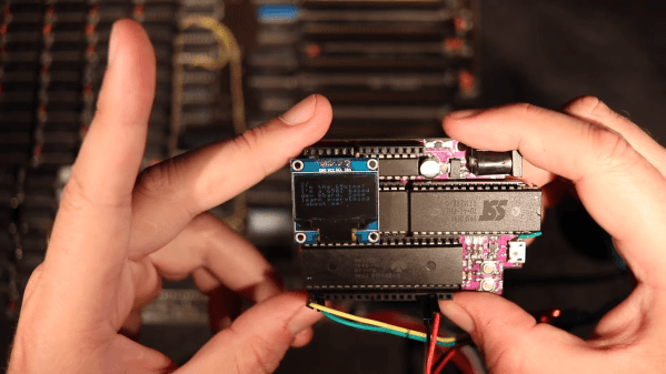
That’s not to say that the size of [Anders]’s game is physically huge either. Flappy Larus, as he calls his game, runs on his popular 65uino platform, a 6502 microcontroller in the familiar Arduino Uno form factor. So it’s pretty small to begin with, and doesn’t even need any additional components other than the tiny OLED screen which has become more or less standard for the 65uino at this point. The only real add-on is a piezo speaker module, which when hooked up to the I2C data line happens to make reasonable approximations of a squawking seagull, all without adding a single byte of code. Check out a little game play in the video below.
Flappy Larus may be pretty simplistic, but as we recall, the game it’s based on was similarly minimalist and still managed to get people hooked. The 2024 Tiny Games contest is closed now, but if you’ve got an idea for a tiny game, we’d still love to feature it. Hit the tip line and we’ll take a look! Continue reading “2024 Tiny Games Contest: A Flappy Seagull Game With Sound In Only 500 Bytes”