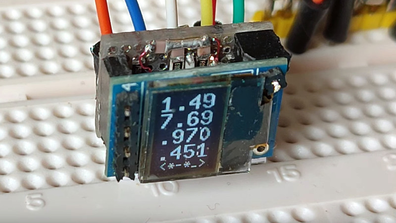
The instrument which probably the greatest number of Hackaday readers own is likely to be the humble digital multimeter. They’re cheap and useful, but they’re single-channel, and difficult to incorporate into a breadboard project. If you’ve ever been vexed by these limitations then [Alun Morris] has just the project for you, in the world’s smallest auto-ranging multichannel voltmeter. It’s a meter on a tiny PCB with a little OLED display, and as its name suggests, it can keep an eye on several voltages for you.
At its heart is an ATtiny1614 microcontroller on a custom PCB, but for us the part we most like lies not in that but in the prototype version made on a piece of protoboard. There’s considerable soldering skill in bending surface mount components to your will on this material, and though these aren’t quite the smallest parts it’s still something that must have required some work under the magnifier.
All of the code and hardware details can be found in the GitHub repository, and for your viewing pleasure there’s a video showing it in action which we’ve placed below.


Neat project and auto-ranging is nice. Bravo.
An old Arduino atmega328P can provide 6 analog inputs directly into a PC over USB via HID (V-USB).
While not a cute POLED, the terminal window can be copied to a text file as a crude recorder. As V-USB is USB 1.1 compliant, the PC-OS and hardware can be very old, even DOS.
https://forum.arduino.cc/t/string-numeric-output-with-v-usb-hid/132654/2
This is a fun little project.
I was wondering if there is any hardware for the auto ranging. The schematic in both the “.sch” and “.png” format have 0 bytes, so that won’t work. In the firmware I see references to a “HighRangePin” and the comment on top explains it’s used to switch input between 1M and 1M + 100k divider, similar to the ubiquitous “transistor tester”. It also further improves resolution by switching the internal reference voltage level. Some thought has been put into this, so again: fun little project.
One extension that can be made is to add a range for negative voltages by switching the HighRangePin to Output / High.
Fixed the schematic files now.
Negative voltages: I did intend to use the DAC output to optionally bias the ADC inputs. The problem is that 0V in will not be converted accurately though it could be calibrated. Also need a DAC pin per channel to avoid cross currents.
Simply using logic H would need some tricky calibration to cope with Vcc drift.
Alun Morris
No, but likely the worst.
Have you seen a smaller one?
It’s not the worst – I made one years ago using 3 digit 0.28in LED voltmeters that is worse!
Cute!
(there, I’ve said/wrote it! )
But jealous of the accomplishment as well.
Lovely bit of soldering. I took don’t hold with all this PCB nonsense either. (In my case because it was quicker to learn how to solder SMD with perf board than in was to get my sodding printer to work)
No coffee for you before the soldering… Great job, and so much smaller IRL