The ULN2003 IC is an extremely versatile part, and with the help of [Hulk]’s deep dive, you might just get some new ideas about how to use this part in your own projects.
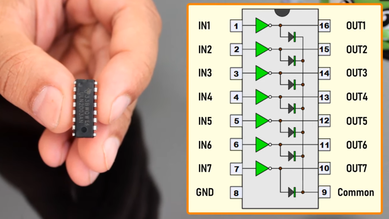
Inside the ULN2003 you’ll find seven high-voltage and high-current NPN Darlington pairs capable of switching inductive loads. But like most such devices there are a variety of roles it can fill. The part can be used to drive relays or motors (either brushed or stepper), it can drive LED lighting, or simply act as a signal buffer. [Hulk] provides some great examples, so be sure to check it out if you’re curious.
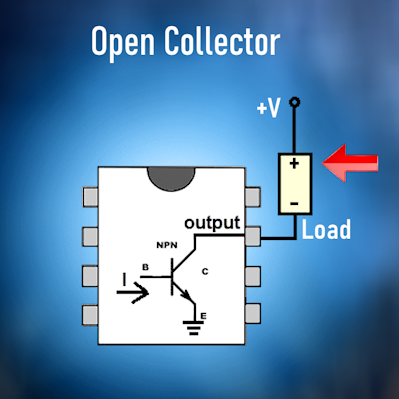
Each of the Darlington pairs (which act as single NPN transistors) is configured as open collector, and the usual way this is used is to switch some kind of load to ground. Since the inputs can be driven directly from 5 V digital logic, this part allows something like a microcontroller to drive a high current (or high voltage, or both) device it wouldn’t normally be able to interface with.
While the circuitry to implement each of the transistor arrays isn’t particularly complex and can be easily built by hand, a part like this is a real space saver due to how it packs everything needed in a handy package. Each output can handle 500 mA, but this can be increased by connecting in parallel.
There’s a video (embedded below) which steps through everything you’d like to know about the ULN2003. Should you find yourself wanting a much, much closer look at the inner secrets of this chip, how about a gander at the decapped die?


The entire chip also has a combined current limit of 600mA so you can’t really parallel the individual transistors for higher output. Even using separate chip packages to increase output current capacity is tricky because bipolar transistors increase collector current with temperature, leading to thermal runaway (transistor handling slightly more current gets hotter and conducts even more current). It’s possible to mitigate this, eg.by individual ballast resistors on each collector, but it’s just easier to use higher rated output device
Get some relays involved.
It’s a simple enough chip that extending it is more complicated than building from discreet components. The sweet spot is where your design fits within the specs of the chip. Like if I wanted to drive 7 LEDs with 50mA+ then it could fit the bill. If I wanted to drive several 1A stepper motors or servos, I might as well build from scratch or find a different chip.
If you wanted to drive several stepper motors, the amount of IO required to address all the coils separately would be the limiting factor. Common driver ICs with simpler step/direction/enable inputs would cut on the IO, but if you really need many then going for a serial bus solution would probably be the best. Plus, you get better microstepping and sine control for quiet operation.
Many moons ago I used these with a PIC C1684 to drive steppers, when stepper drivers were unaffordable for tinkerers and priced for industry, stacking one above another increased load capacity. Although experts will no doubt say it was the wrong way to drive steppers, it worked for me. This was when dancad3d (shareware) was a pioneer in cnc for hobby use.
i think you meant ‘discrete’…
the life of a grammar cop is a lonely one…
>The entire chip also has a combined current limit of 600mA
No it doesn’t.
“Total emitter-terminal current –2.5 A” means it can sink 2.5 Amps through the outputs. This is a thermal limit by the power consumed in the darlington pair (~4-5 W).
There is a “Package Maximum Collector Current” that applies at 70 C which dictates that at elevated temperatures your thermal limit is reached at approximately 600 mA average for the entire device. You can still get by at 2.5 Amps if your duty cycle is 10% or less.
And, looking at the datasheet, you’ll find that the recommended thermal design limit is 125 C (150 C max) and the junction to case thermal resistance is 50.1 C/W. The forward voltage loss is about 1.5 Volts at high current, so with an adequate heatsink you can drive it at 1.3 Amps at room temperature, indefinitely. You’ll still have a good 25 degrees of headroom for overheating.
As always, it pays to read the datasheet thoroughly.
More precisely, if your design demands 330 mA per output, your forward voltage drop would be about 1.2 V and the maximum sustained current you can drive for the thermal limit is about 1.7 Amps at room temperature, with a heatsink.
Without a heatsink, the thermal resistance of a DIP-16 package to ambient air is about 56.2 C/W, which limits your sustained current to about 800 mA. This may be an issue if you’re putting the device in a sealed box where the internal temperature can rise to 40-50C, but then again, why would you be doing that for a Darlington device that you know will get hot?
The current is shared equally between the paralleled outputs, because the forward voltage drop of each C-E pair increases with increasing current, so there’s a negative feedback effect going on.
> because bipolar transistors increase collector current with temperature, leading to thermal runaway
You’re assuming linear mode, where the transistor is used to limit current, for example when driving LEDs without ballast resistors. This wouldn’t be stable without feedback to control the base current, and even less so with a high gain device like the ULN2003. It is also not how you use this device: the transistor is just a switch, the current is limited by the load, not the transistor.
With the transistors in saturation, you want it to pass as much current as possible. If there is any negative temperature coefficients that would increase the collector-emitter current, with the load as the current limiting element, it would mean that the collector-emitter forward voltage has to drop so the load could pass more current. This results in a net zero change in heating power, since it’s a product of both the collector-emitter current and the forward voltage loss. One goes up, the other goes down.
In fact, since the collector-emitter forward voltage increases more or less linearly to 1.5 Volts at 500 mA (fig 5.14 in the datasheet), you have a negative feedback effect for the load current. It’s self-regulating when used as a switch.
It’s a handy chip. I didn’t realize they were still made.
I like the ULN2803 a bit better, because it has 8 outputs which is a nice round binary number.
There are also variants with high side switches but I can’t remember their type numbers.
And then there are parts such as the TPIC6C595. It’s basically an HC595 shift register, but with open drain outputs that can have 100mA DC and voltages up to 33V
On the other side, the big DIP packages are getting obsolete. There are lots of bipolar resistors with built in base (& Base-Emitter) resistors (so a one channel ULN2003) but in small packages such as SOT-23 and smaller, or two of them in an SOT23-6. As a result those can be packed denser on a PCB then the ULN. And of course also singular MOSfets that have logic compatible inputs. It’s quite common for those to switch several Amps inside a SOT-23 package.
There are many solutions for similar objectives.
Diodes Incorporated appears to have picked up production of the otherwise obsolete ULN2003A. The Darlington open collector drivers are rated for 500 mA at up to 50V switching. The are internal diodes to neutralize the inductive kick-back of inductive loads, so it is a handy part for reducing component count. The ULN2003A is designed to be a low side driver, connecting loads to ground when the corresponding input is TTL/CMOS high. I ran across several people grumbling the maximum and current sinking are less with the Diodes equivalent part, but the data sheet shows the same specs as the original.
There is a complimentary part, UDN2983A which is a high side driver. The UDN2983 is designed to connect a grounded load to V+ via a Darlington pair with open emitter when the corresponding input is TTL/CMOS high. Similarly, diodes are provided from the open emitter to ground to shunt the reverse voltage generated by switching inductive loads.
A modern similar MOSFET low side driver is the TPL7407LA, though the nominal current capability and maximum voltage are lower.
Ease of design, lower part count
“… obsolete ULN2003A.”
or not. It’s still listed as active with TI, ST and onsemi.
Is there any particular reason why, for general tinkering, I would stock these instead of having a pile of MOSFETs for the same sorts of application?
ase of design, lower part count
It has direct 5 Volt TTL/CMOS compatible inputs for a micro-controller, whereas MOSFETs generally need around 8-10 Volts to open properly, or have high gate capacitances for logic level devices, which results in either high switching current consumption, demanding a drive buffer, or low speed switching and high transition losses.
Darlingtons switch fast and easy, so they’re nicer for driving PWM loads when you don’t mind the slight voltage loss in the switch.
For low demands, you’re better off with a simple cheap “fettington” like the BS170, MMBF170. They come in TO-92 package, so you hit the thermal limits very quickly though.
Basically, the ULN2003 sits in the middle ground where you need moderately high currents, simple driving, and multiple outputs in a single device. With MOSFETS, you need to faff around with diodes and resistors, and finding the right part can be time consuming.
Switching losses would pale in comparison to the Vsat of a Darlington pair.
By switching current consumption, I was referring to the controlling side – the power demand out of the microcontroller.
And If you drive a logic level MOSFET with a large gate capacitance too slowly in a H-bridge configuration, you get shoot through (transition loss) which results in high current spikes and can damage the FETs. Avoiding this requires you to add dead time in your drive signals, so the transistor can close before the opposing transistor opens.
It’s these sort of details that often bite the amateur tinkerer, because they don’t know to expect them – yet.
Also, when driving MOSFETs, although they’re considered to be voltage controlled devices you absolutely need gate resistors, because the gate is a capacitor and represents a dead short to ground (or V+) for a short moment when the transistor is off. If you’re driving it directly from the micro-controller, the current surges can cause power glitches or damage the controller.
Here’s one thing the video doesn’t mention: the ULN2003 and similar ones such as the 2803) are normal darlingtons that can be biased in their linear region. I built a working *audio* preamplifier back in the day using one of them. Also, by coupling the darlingtons together, either at their collectors or grounding the emitter with a low value resistor (de facto making 7 emitter followers) one could build a 7 input audio mixer. Performance won’t be HiFi of course, still interesting for learning purposes.
A mddern replacement for the ULN2003 is the TBD62003APG, which is what I started using after I found my UL2003s tended to die very five years or so (sometimes spectacularly auto-decapping). A TBD62003APG is the heart of my off-grid cabin’s remote control system, allowing me to dump surplus electricity into high-energy loads once the battery is full:
https://github.com/judasgutenberg/Esp8266_RemoteControl
The ULN prefix indicates that the device was first produced by Sprague Electric.
>>seven high-voltage
What I’m I missing when I look at the datasheet? 50V on the output is what I see, which is wimpy AF!