While we generally prefer to bring our readers as much information about a project as possible, sometimes we just have to go with what we see. That generally happens with new projects and work in progress, but it can also happen with old projects. Sometimes very old indeed, as is the case with this digital sampling unit for analog oscilloscopes, circa 1979.
We’ve got precious little to go on with this one other than the bit of eye candy in the video tour below and its description. Luckily, we’ve had a few private conversations with its maker, [Mitsuru Yamada], over the years, enough to piece together a little of the back story here — with apologies for any wrong assumptions, of course.
 Built when he was only 19, this sampler was an attempt to build something that couldn’t be bought, at least not for a reasonable price. With no inexpensive monolithic analog-to-digital converters on the market, he decided to roll his own. A few years back he recreated the core of that with his all-discrete successive approximation ADC.
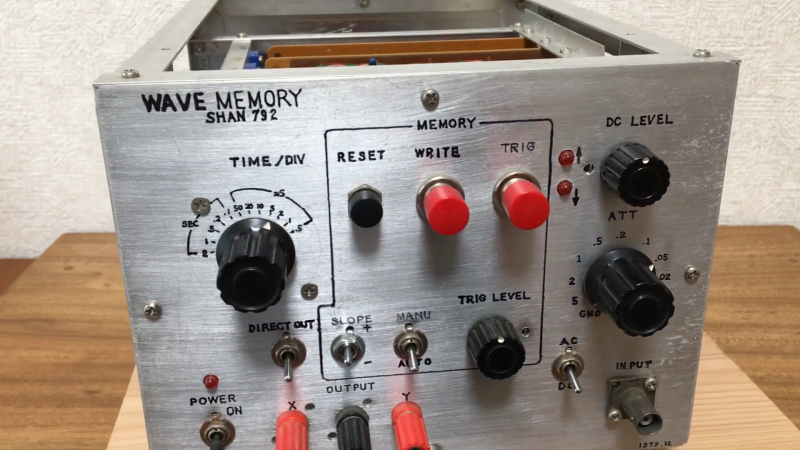
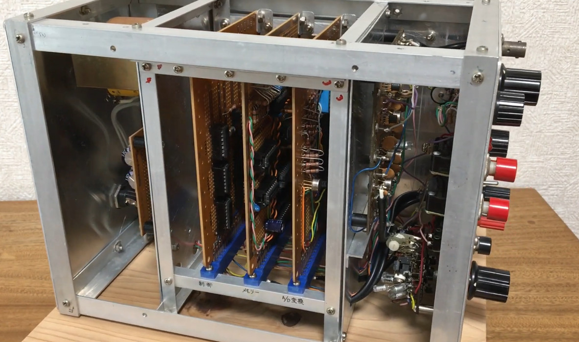
The sampler shown below has an 8-bit SAR ADC using discrete CMOS logic and enough NMOS memory to store 256 samples. You can see the ADC and memory cards in the homebrew card cage made from aluminum angle stock. The front panel has a ton of controls and sports a wide-range attenuator, DC offset, and trigger circuit with both manual and automatic settings.
It’s an impressive build, especially for a 19-year-old with presumably limited resources. We’ve reached out to [Yamada-san] in the hope that he’ll be able to provide more details on what’s under the hood and if this still works after all these years. We’ll pass along whatever we get, but in the meantime, enjoy.


The most impressive thing is the lettering.
It’s all so easy now, I’ve got at least three machines at home which I can use to make professional looking front panels, there’s any number of services out there I can pay reasonable sums of money to which will do the same.
Sometimes I wish it weren’t so easy so that we’d see more handmade efforts and I certainly wish I could produce hanade panels to that standard.
I remember seeing something like this in Popular Electronics magazine, late 70’s.
The hand-drawn drawings and photos of the board from that time can be found in the attachment of the Hackaday.io project linked in this introductory article.
I retrieved it stored in my native house and after 40 years of trying to test its operation, I found that it has multiple glitches and AD conversion is not converging properly. And now I did not have an analog oscilloscope at hand, so I tried to display this output on a digital oscilloscope, albeit imperfectly, but it was not going to impress me at the time.
Thank you for sharing. Very professional looking, both finish and the component layout within.
I have been doing electrical engineering all my life and I know for sure that I could not have done this when I was 19. It’s a beautiful piece of work, and thank you so much for sharing it with us. I hope you had a career that allowed you to use your EE talents.
At the time, I was able to figure out on my own, before I learned, that aliasing occurs when the input signal frequency exceeds half of the sampling period in this home-built device. I ended up getting a job designing and developing digital signal processing for scientific equipment. It was hard work, but I was able to get a PhD in signal processing from the university while continuing to work. I am still working on development projects that are at the interface between electronics and physics. Even now, I seem to be characterized by the fact that I suddenly build prototype devices on my own.
I remember learning about the methods for analog to digital conversion during my EE education, but I’ve never attempted to build one from scratch. This is so cool to see, thank you for sharing.
It seems that, like myself (only I never did a Ph.D.), you are enjoying your work! There are very few of us, and I always feel like I got away with something: getting people to pay me while I was having fun doing what I enjoyed :-) I worked (still do, but not full time) for a design consultancy, helping our clients develop products and solving technical problems for them.
Just compare this glorious machine to its modern contemporaries. It is similar to the sampling feature of the Boss DSD3, which could store and playback a sample when a trigger was input. Overall this is a component of a digital delay if you loop the sample playback and continuously overdub onto this delayline, this device is like the grandfather of the PT2399.
This reminds me of the SAD-1024 sampling analog delay line IC I was playing with around that time. It had two 512-element bucket brigade analog shift registers, clocked at multi-kilohertz rates to produce reverb and other effects. It could “store” a sample for a fraction of a second.
I don’t think I ever tried stopping the clock to see how long it would remember the stored sequence of samples, but it didn’t work very well to just recirculate the sample to “store” it: after a few seconds it would degenerate into a bad oscillator or noise generator.
I must have got the thing at Radio Shack. It was the only game in town at the time. They had several weird chips to discover and play with, like sound effects generators and (later) phoneme-based voice synthesizers.
Geez, now I have to go look through some old boxes to see if I still have any of those projects… (after 45 years and 12 household moves through 3 countries, I almost hope not.)
I have posted a detailed description of this digital sampler, including videos of it in action and the schematics, as ‘Homebrew Digital Sampler in 1979’ in my Hackaday.io project.