Recently [Stefan] of CNC Kitchen took a gander at using his gaggle of 3D printers to try injection molding (IM). Although the IM process generally requires metal molds and specialized machinery, 3D printers can be used for low-volume IM runs which is enough for limited production runs and prototyping before committing to producing expensive IM molds. In the case of [Stefan], he followed Form Labs’ guidance to produce molds from glass-infused Rigid 10K resin (heat deflection temperature of 218 °C). These molds are very rigid, as the ceramic-like noise when [Stefan] taps two together attests to.
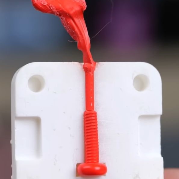
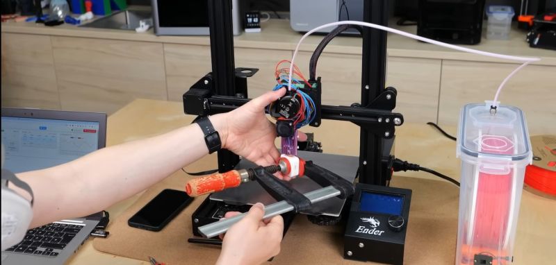
The actual injection process is where things get more hairy for [Stefan], as he attempts to push the clamped-shut mold against the nozzle of the FDM printer to inject the molten plastic, rather than using an IM press. With PLA at standard extrusion temperature the plastic barely gets into the mold before solidifying, however. Following this, higher temperatures, different materials (PETG, TPU) and high flow-rate extruders are attempted, with varying results.
Many of the struggles would seem to be due to poor mold design, rather than fundamental issues with using an FDM. The Form Labs document details some of the basics, such as opening up the injection gate (to decrease pressure inside the mold), adding air vents to improve flow and so on. Commentators to the video with professional experience point out many of these issues as well, along with the benefits of preheating the mold.
With the caveat that most of the challenge is in making a good mold, we’ve even injection molding done with nothing more exotic than a hot glue gun. If you’ve got a friend, or a long enough lever, you can even inject the plastic by hand.


Soon we can make LEGO at home!
you would be better off with a pourable resin than attempting it this way. 3d printers do not extrude with sufficient pressure nor speed to fill thin wall parts
For prototyping, use a caulk gun and construction silicone.
If you need more pressure, use grease gun bodgged full of silicone and zerk fitting on mold. 10,000PSI silicone reachable, just disassemble grease gun after (or dispose HF junk).
Consider using better silicone and vacume bucket.
If you actually intend to ever actually IM with hot plastic:
The gate (injection port) is in the wrong place.
Should be through one of the sides, not between them. (This is the injection side, the other is the ejection side).
Waste plastic sprew should be tapered to come out on injection side with part when mold opens.
Good sized cold well just before the breakpoint on the ejection side opposite the taper. The ‘cold well’ is for the coldest part of the hot plastic shot to collect, rather than in the part. If you’ve ever seen a plastic model kit, you’ve seen many cold wells. The big apparently useless lumps on the sprew.
Sprew should be dead simple. Tapered injection side, round bottomed cold well, maybe with ejection pin under, passage meant to break off (when cold) connecting sprew to part.
Fill passage should be at middle of part volume, not one end. Consider weld areas.
The side not being used for gate should have a feature (tiny overhang, about 5-10 thou, less if large) that keeps the part attached and should have ejection pins under part (used to knock it out of the open mold). These pins have to be located during molding or you get round protrusions on part. Hence ejection plate.
Simple injection molding was all worked out more than 100 years ago.
Also: The reason they use moving screw/barrels rather than extruders on injection molding machines is that melted plastic is a _compressable_ liquid! Parts cooled while compressed are stronger! Whole shot melted and injected in a half second also helps, a lot.
Until recently controlling pressure on the mold with an extruder was flat impossible, You’re not going to reproduce that work on your first machine.
Wow! I’m impressed by the knowledge you just presented!
The commenter isn’t an expert, and I’d be surprised if he has ever injection molded.
1) injection mold cavities are gated frequently using BOTH sides of the mold.
2) No ejection pins are used, so no need fo ‘overhangs’ to keep the part on one side.
3) It is a CENTERLINE INJECTION, not a hot side/cool side situation, my friend.
4) Cold wells are not needed when you gate DIRECTLY INTO THE PART
5) SPRUE, not “sprew”
6) These molds have NO ejection pins, hence no ejection plates. Very common in prototyping.
..but I agree that using 3D printer extruder as an injector is a horrible idea.
Frequently? You’re nuts.
Most machines are still dead simple. One barrel jobs. Even when overmolding they just use a robot to move the part to the next machine.
My spelling sucks. Fair point. F U.
There is a big old world of types of injection molding. I’m sure you can find centerline injection somewhere. Slides in the mold are a more common solution to the problem.
My point was the author hasn’t studied the basics (worked out about 100 years ago) before setting out to reinvent.
The parts you are criticising are all after ‘If you actually intend to ever actually IM with hot plastic’.
Are you building actual prototype mold cavities with no ejection pins/sleeves and no pull groove/thought to which side the part was going to stick to?
Hot brass screw trick?
Seems like a wasted iteration, I’d just include ejectors in rev0. Not like they’re the expensive part or missing from any of the bases.
Your going to need a hotspru or a cold well. Even the hottest preheated mold is cold compared to the shot.
Tricky to get the nozzle into the moldbase, right on the back of the cavity, but I’ve done it. Small business, you do what you have to. Ugly hack.
Injection side of mold is not hotter then the ejection side. Excepting the possible hotspru itself. Unless something is very wrong.
I don’t know where you got ‘hot/cool side’ from.
Idont understand why he didnt use venting holes and press the mold with the hand instead use the hot bed as platform
Its fun to play outside the box. In this case I wonder if an extruder head for a defunct 3D printer moundered on a arbor press would be easier to use. Or add a post and mount the extrude head into a drill press.
@HaHa has the most useful information here. Spend some time looking online at temperature profiles in injection molding and you’ll see that the heating/cooling of the molds themselves is critical for part formation. Mold making, temperature regulation/cycling etc. is a whole field of applied science and an industry unto itself.
https://www.ptonline.com/articles/the-importance-of-melt-mold-temperature
I wonder if you could design a part with a hollow channel, print it, then fill the hollow channel using this method?
Like, if you make a tall thin object, you could have layer adhesion issues, so what if you made it hollow and then just filled it in?
Thats a really great idea. The only problem is, the hollow part has to be temperature resistant to the point the other material melts at.
Does it? If the walls of the hollow part are thick enough, the new liquid plastic won’t have enough energy to melt most of it.
I’m imagining like a 5mm wide part with a 2mm wide hollow part, all PLA with the same exact PLA to fill it in.
You propose to make a tall part more difficult to print so that you can later just pump more plastic into the void to fill it?
You realize a hollow tall part is going to be harder to print than a ‘solid’ tall part? As you say, layer adhesion.
That your going to need a much bigger extruder to have any hope of filling the part. You have no hope of getting the fill to pressure.
If you need a strong part, print it with a hollow sized to fit an aluminum rod/extrusion. Only print the ends if it needs to be very tall. Duh.
Thats a really great idea. The only problem is, the hollow part has to be temperature resistant to the point the other material melts at.
With a 3D pen, it is even cheaper for low production of small parts!
In India 1kg of recycled PLA (r PLA) filament can be bought for $5!
Hi all.
Have been looking at video .
And liked it .
Very interesting idea that I hadn’t thought of .
Have been injection moulding for last 25 years and 3d printing for 5years. There are machines that do this type of prototyping all ready which are called a manual mould and also the hand press injection moulder.
But they cost from £500 up.
The problems he was having filling the mould was because of the temperature difference between the extrusion plastic and the mould 3d printing plastics are designed to harden quickly to reduce droop and warp.
Where injection plastics are made to stay molten to some extent so they can fill the tool.
Tools are kept cold to cool plastic quickly to reduce cycle time.
As for spruce placement it can be anywhere needed .
Manual mould and hand moulders have split line sprue usually and injection moulding has a sprue bush that goes through the middle of the tool into its Center
As for ejector pins most injection moulds have ejector pins as they are made to run repeatedly for days at a time.
But a lot of manual moulders and hand moulders don’t have as they are made for the lower volume market.
I have several tools that have no ejector pins and have a person loading inserts and unloading the product manually .
This is on manual moulding and also on injection moulding.
Looking at how he clamped the mould together he probably needed a vent at the bottom of the tool to allow air to escape from tool as the plastic was extruded in to it.
Also the nozzle on the extruder needs to be made more into a cone that the mould fits. As to reduce the leaking plastic.
TPE works well as it’s a high flow low temp plastic.
Loved the video and will be trying this my self to see how it works I’m always looking for a cheaper way of prototyping. I own 14 injection moulders and 3 manu moulders
And a cheaper way of producing a few sample product is always worth looking into.