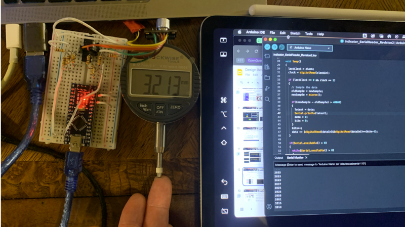
If you’re instrumenting your machine tools, or if you’re just curious, you might want to get granular access to the output of a digital micrometer or the like. [Tommy] set his mind to figuring out the communications protocol of the ClockWise Tools dial indicator for this very purpose. And he succeeded!
Work began by finding the clock and signal lines for the gauge. With those identified, and the signals up on an AD2 logic analyzer, it was determined that once every 40 milliseconds, the device sent a data burst of six nibbles separated by 1.58 milliseconds apiece. The device communicates the absolute position of the gauge, and the data can be readily decoded with the aid of an op-amp to help boost up the 1.5-volt logic to a more reasonable level for a modern commodity microcontroller like the Arduino Nano. From there, the information can be trucked over serial to a PC, or you can do just about anything else with it besides.
We’ve seen similar hacks performed on calipers before, too, making automated measurements a breeze. If you’re working on something that needs precise measurements down to the, well… micrometer… this project might be just the thing you’re looking for.


It gives me hope that I can fix my broken 1 meter Mitutoyo caliper.
Replacement circuit board is no longer available.
just dropping in to let everyone know bluetooth calipers are now reasonably priced
Clockwise/VINCA [1] just takes devices cheaply made in Asia, marks them up by a significant amount, then resells them to suckers on the likes of Amazon without adding any real value. The fact that [Tommy] had to reverse-engineer a Clockwise/VINCA branded tool to read out data from an undocumented interface that already exists, proves this point. Why doesn’t Clockwise/VINCA just freely and openly publish the existing interface specifications? Making the interface specifications known to all will help make the existing interface become a defacto “standard” and boost sales dramatically – which would benefit everyone – right? Nope! Looking at all the work [Tommy] had to do to access the data, it seems not. So what’s next? Clockwise/VINCA hiring a greedy Trial Lawyer to sue [Tommy] and make him pull down the interface specification information under the DMCA? Sheeesh…
1. Clockwise/VINCA Tools
https://clockwisetools.com/
Be careful: op-amps can be quite slow for digital data. It would be better to use a comparator or a level-shifter buffer meant for the task rather than relying on the slew rate of a high-bandwidth opamp.
Yup, and I’ve level-shifted serial data with just a PNP transistor and a couple of resistors. The signal is inverted but that doesn’t matter since you’re interpreting the signal with an Arduino anyways.
Wat? Analog does not work that way. What is a digital signal but a bunch of high order harmonics anyway?
If you are encountering signal distortion its cause you chose a poor slewer, blew it up or are not using it proper. all logic flip flops are opamps, are they slow?
If I recall correctly, the protocol is closely related to the one used by Chinese calipers and micrometers.
I also own one (a generic Chinese version). Mine came with a RS232 converter, however.
https://hackaday.io/project/511-digital-dial-indicator-cnc-surface-probe and https://github.com/stawel/dialIndicatorToSerial
Same with all of mine. I’ve not tested it yet, but it states in the documentation it is RS- 232. I’ve tested mine with B&S gauge blocks. Dead on to a half tenth or 1 micron. Around $20 IIRC delivered.
do you have any idea about asimeto dial indicators?
Older units which take LR44 batteries often have an adjacent port which in some cases has a connector (possibly RJ series) which is described as RS232… albeit obviously at a lower voltage.
https://www.aliexpress.com/item/1005007916363187.html is a good example, with variants from 11.7 to 25.4mm resolving 0.01 or 0.001mm.
I think it’s probably reasonable to assume that any of these with two hatches on the top- even if one is blanked off- has serial data on the PCB.