Although marketing folk and laypeople may credit [Steve Jobs] as the man behind the success of Apple, those in the tech world know the real truth that without [Steve Wozniak] nothing would have ever gotten off the ground during the early days of the computer company. As an exhibit of his deep knowledge of the machines he was building, take a look at this recreation of a circuit by [Anders] which allows the 6502 processor to step through instructions one at a time, originally designed by [Woz] himself, even though there are still myths floating around the Internet that this type of circuit can’t work.
Like a lot of Internet myths, though, there’s a kernel of truth at the middle. The original 6502 from the mid-70s had dynamic registers, meaning they would lose their values if the chip was run below a critical clock speed. Since single-stepping the processor is much lower than this speed, it seems logical that this might corrupt the data in the registers. But if the clock is maintained to the registers the processor can be halted after each instruction, allowing even the original 6502 to go through its instructions one at a time.
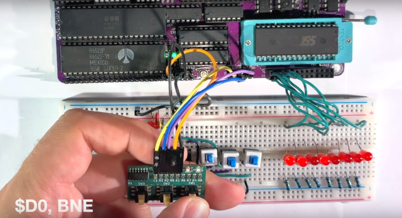
[Anders]’s project sets up this circuit originally laid out by [Steve Wozniak] but updates it a bit for the modern times. Since the technology of the era would have been TTL, modern CMOS logic requires pull-up resistors to keep any inputs from floating. The key design of the original circuit is a set of flip-flops which latch the information on the data bus, and a switch that can be pressed to let the processor grab its next instruction, as well as a set of LEDs that allow the user to see the value on the data bus directly.
Of course, a computer processor of this era would be at a major handicap without a way to debug code that it was running, so there are even dedicated pins that allow this functionality to occur. Perhaps the Internet myth is a bit overblown for that reason alone, but [Anders] is no stranger to the 6502 and has developed many other projects that demonstrate his mastery of the platform.


Way back in the early 1980’s I worked at a place repairing the control boards for printers. The printers were wildly popular and I still see one in use here and there even today.
On a lot of them the issue was obvious. The common ones were print head pins not firing, the platen not advancing, or the print carriage freaking out. We got really good at knocking those out.
There was another whole class of problem, they were the ones that would do little or nothing. We would do the obvious easy thing, swap out the Z80 cpu and EPROM and that would revive some of them, but some had more deeply rooted issues.
We had another job that was just closing out and we had a reel of those near HP “dot” displays that took 4 binary bits and a strobe and would display 0-F on the display. So I got the bright idea of making a box with a bunch of them to read off the data and address bus. The thing was though, it had to be slowed way down. The initial thought was after a while you would get to know the first bunch of things it did as it did it’s POST and init.
Sadly, it turned out that you could not single step the thing, and even driving it with a function generator instead, it was dead in the water until far above where you could make any sense of the displays.
It was an interesting experiment but even if it worked most of the tine it was a crapshoot as you would find something pulling one one bit on one of the busses up or down and of course every device on the thing shares the bus. We got to know likely parts from just doing a lot of them, but it got so you would just start nipping that on every chip until the situation was cleared. Than take the board to the poor rework line with a whole bunch of tagged chips with one leg cut off to be sucked out and replaced.
I have several boards with those HP dot displays.
For 35 years I have been planning on doing something with them.
(Sigh)
They do use a lot of power though.
I just ran across some devices in my “collection” that use those teeny magnified LED 7 segment displays. Wondering what I might do with those. Most likely, it will be something very similar to what I did with them before I realized I had them.
Hpmuseum.org Forum often has people searching for replacement displays for the old calculators. If yours are the right type, they’re willing to buy.
Back in the mid 80’s I recovered a fist full of those displays from scrap. As digital freq counters were still quite expensive, I built one with those displays, some TTL counters, and a 1 Mhz crystal.
Here’s something of that general nature that messed with back in the day:
You take the top 8 bits from the address bus and feed it to an 8-bit D/A converter. Take the low 8 bits from the address bus and feed them to a second converter. Now, connect the output of the first D/A to the X-axis of your o-scope, the other to the Y-axis.
You’d be surprised how quickly you can develop intuition as to what a cpu is doing, simply by looking at Lissajou patterns. You can easily distinguish between a dead processor, one running a linear stretch of code, and one hung in a loop, for example
That Is Awesome! I’ve got some sperimentin to do, Thanks!
A Z80 is much easier to single step as it is a completely static processor. I did this in the 80s. Then I took some 9368 4-bit binary to 7-segment hex encoders and red 7-segment LEDs that showed the hex codes of both the data and the address.
Yes, the z80 was quite a bit more advanced than the 6502 on release, but that did come at a cost, around 4 times the price. Not only did the z80s nmos design come with static registers from the start, but built in refresh circuitry for your external dram. It certainly gave Intel a run for their money.
The 6502 on the other hand was targeted as a low cost budget cpu. It was still very capable, despite the engineering tradeoffs to do so. It would be a few years later they released their cmos 65c02 with static registers allowing a 0hz clock. If it wasn’t for the popularity of the original, that chip might not have happened.
I enjoyed the video. Without reading his YT comments, I am guessing his next project will be an Apple 1.
Thanks for the great video. I am debugging machine language on a 6502 CPU with a single step operation similar to this one. I am able to manually access the bus using toggle switches in the stopped state to write all programs, and I am able to manually do all debugging while checking the execution address progression and zero-page register memory values during execution in the step operation.
In my case, the circuit consists of two JK-FFs and a NAND gate. And in my case, when I do CPU RESET with the CPU stopped, in rare cases the RESET sequence is not performed correctly, so I added a circuit to keep the CPU in RUN state during the RESET period.
I wonder if this could be hacked into the BBC Microcomputer?
Doesn’t the modern version of the 6502 support single-stepping natively?
Yes. WDC’s W65C02S can be stopped indefinitely in either phase of the clock, without losing the registers. Other manufacturers’ CMOS 6502’s (65c02’s) could be stopped indefinitely with the clock high, but not low.
i’m astonished that on the stm32, if you have the ICD adapter (which is built into the ‘value line discovery’ boards) then fully-featured interactive gdb is actually the easiest way to interact with the thing. i even use breakpoints and memory side-effects through gdbserver for I/O. but that’s just a contrast to huge families of development where i just assume there’s no debugging. printf debugging or its cousin, toggle a couple GPIO lines, maybe with LEDs if you’re lucky.
i’m just having a hard time wrapping my head around anybody being at a disadvanteg 40+ years ago for not having an instruction-level debugger…in my imagination — maybe i give up too easily — good low-level debuggers are a modern novelty, and ‘just make do’ rules the day.
What’s that fuzz all about?
Single-stepping was built into the 6502 from the beginning, that’s why it has the Ready (RDY) input. A circuit to use it was published in MOS Technology’s literature (MCS6500 hardware manual 2nd ed., p.125). Wozniak built a simplified version of that circuit.
That was to make it wait another cycle or two for slow memory; but you still couldn’t stop the NMOS 6502 indefinitely.
Regarding the RDY signal, MOS Technology’s datasheets from 1976 explicitly state “This input signal allows the user to single cycle the microprocessor …” before mentioning other uses. Suspending the CPU in a synchronized manner should incur no data loss with internal (dynamic) holding registers, because the stored data was only relevant for one clock cycle which already occurred. Also there is no upper limit on how long you can hold the CPU in this state as long as the clocks keep running.
Of course you cannot single-step by stopping the clocks, as this would certainly confuse the clocked logic which was highly optimized for silicon real-estate and used parasitic capacitances instead of conventional storage elements wherever possible. But this is the case with practically all NMOS-CPUs of that era, like 8080, 8085, Z80, 8086, 68000, just to name few.
There’s an old chat system called Diversi-Dial. It was written in 6502 I believe.
You can find a modern version on magviz.ca
I bought the program, an Apple //e, and 7 Transcend 300 baud modems.
I booted the 5.25 floppy diskette, and sent the program to the Apple //e’s cassette port
that had a tape recorder connected to it. Once the program was done being sent to cassette,
the //e was shut down, unplugged, and the peripheral cards were removed from their slots.
To this day, I miss running that system, but there are still many “dialers” around.
You can go to magviz.ca, or ddial.com. Have fun. :) See you there.