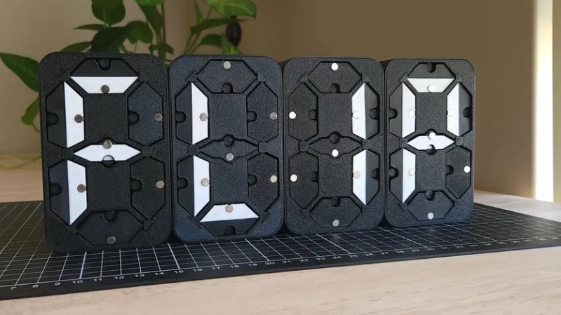
The seven-segment display is most well known in LED form, but the concept isn’t tied to that format. You can build a seven-segment display out of moving parts, too. [tin-foil-hat] has achieved just that with a remarkably elegant design.
As you might expect, the build relies heavily on 3D-printed components—produced in white and black plastic to create a high-contrast display. It’s a simple choice that makes the display easy to read in a wide variety of lighting conditions, and far less fussy than toying with LEDs and diffusers and all that.
Actuation of each display segment is achieved electromagnetically. Effectively, each segment behaves like a flip dot, with the orientation controlled by energizing one of two electromagnets per segment. Controlling the electromagnets is an ESP32, which is hooked up to the various segments via a Darlington transistor array, with multiplexing used to minimize the number of IO pins required. A shift register was also employed to let the microcontroller easily drive four of these electromechanical digits.
It’s a simple build, well explained—and the final result is aesthetically pleasing. We’ve seen a few builds along these lines before, albeit using altogether different techniques. Lots of different techniques, in fact! Video after the break.
[Thanks to Archivort for the tip!]


so i watched this one. He stated that it was much easier to design a pcb that only pushed current in one direction, but had to do it twice for each segment. Is it really easier than using a bidirectional motor driver? i’m doing a similar project using pager motors instead of magnet fields.
It looks like each segment has 2 coils. At any time, he’ll energize only 1 coil, so it’s almost like a single pole, double throw switch, or like a flip flop. But for a motor you’d have an H-bridge, which is essentially a double pole, double throw switch.
His setup would work if you have two motors that you want to switch on or off, without controlling the direction. If you want to control the direction, you’ll want a motor driver/H-bridge, or stepper motors.
If you have a common middle rail, it’s possible to use a single H-Bridge to drive two coils in two directions, or four coils in one direction using diode steering. The bridge IC just needs to have separate A, B and Enable inputs for it to work.
It’s possible to make this circuit much simpler and more elegant. First of all, the relays are completely unnecessary.
Essentially, what you’d do is use the H-bridge as two half-bridges with three possible states: high, low, and off (high impedance). There are chips that are just multiple half-bridges where each output has a separate logic input and an enable input, so you can implement a three-state buffer.
This is much more versatile than the ULN2xxx darlington bridge + relays used here.
If you want to amp up the contrast then using black 3.0 on the black parts with do it. I’m sure there is also a superwhite of some sort and then you would ultimate contrast.
Great explanation video
Now we just need to scale this down to a PCB magnet and get a flat display like a previous flip clock article!
https://hackaday.com/2024/11/05/split-flap-clock-flutters-its-way-to-displaying-time-without-numbers/
Like that: https://hackaday.com/2025/06/23/modern-tech-meets-retro-7-segment/ ?
Hate the embedded add for PC board vendor that gave him free boards. It seem YouTube has turned content makers into prostitutes.
you’re welcome to set the example and upload videos of your projects you build out of your own money. they wouldn’t be able to even get close to you, so high on your horse!
They need to pay bills someway
What I don’t get is the white flaps are only half filled, would have looked “brighter” if that side was all white?