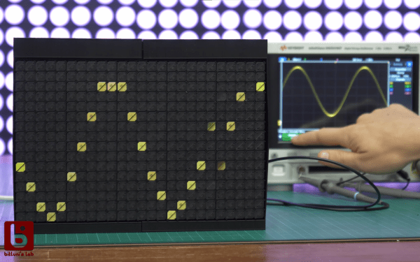
The seven-segment display is most well known in LED form, but the concept isn’t tied to that format. You can build a seven-segment display out of moving parts, too. [tin-foil-hat] has achieved just that with a remarkably elegant design.
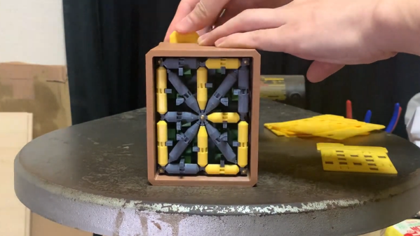
As you might expect, the build relies heavily on 3D-printed components—produced in white and black plastic to create a high-contrast display. It’s a simple choice that makes the display easy to read in a wide variety of lighting conditions, and far less fussy than toying with LEDs and diffusers and all that.
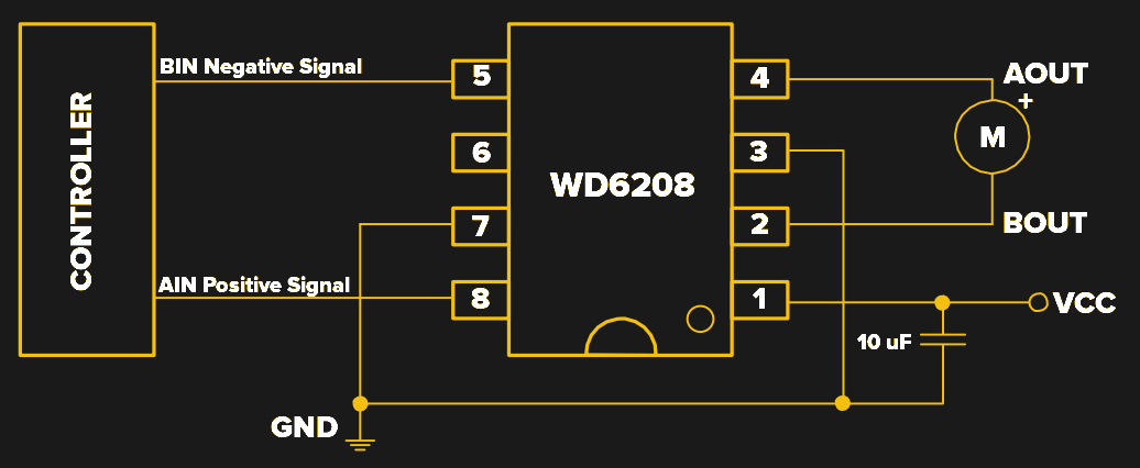
Actuation of each display segment is achieved electromagnetically. Effectively, each segment behaves like a flip dot, with the orientation controlled by energizing one of two electromagnets per segment. Controlling the electromagnets is an ESP32, which is hooked up to the various segments via a Darlington transistor array, with multiplexing used to minimize the number of IO pins required. A shift register was also employed to let the microcontroller easily drive four of these electromechanical digits.
It’s a simple build, well explained—and the final result is aesthetically pleasing. We’ve seen a few builds along these lines before, albeit using altogether different techniques. Lots of different techniques, in fact! Video after the break.
Continue reading “Electromechanical 7-Segment Display Is High Contrast Brilliance”