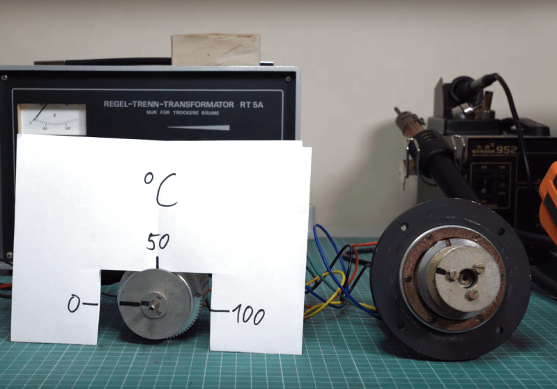
Before the digital age, when transistors were expensive, unreliable, and/or nonexistent, engineers had to use other tricks to do things that we take for granted nowadays. Motor positioning, for example, wasn’t as straightforward as using a rotary encoder and a microcontroller. There are a few other ways of doing this, though, and [Void Electronics] walks us through an older piece of technology called a synchro (or selsyn) which uses a motor with a special set of windings to keep track of its position and even output that position on a second motor without any digital processing or microcontrollers.
Synchros are electromagnetic devices similar to transformers, where a set of windings induces a voltage on another set, but they also have a movable rotor like an electric motor. When the rotor is energized, the output windings generate voltages corresponding to the rotor’s angle, which are then transmitted to another synchro. This second device, if mechanically free to move, will align its rotor to match the first. Both devices must be powered by the same AC source to maintain phase alignment, ensuring their magnetic fields remain synchronized and their rotors stay in step.
While largely obsolete now, there are a few places where these machines are still in use. One is in places where high reliability or ruggedness is needed, such as instrumentation for airplanes or control systems or for the electric grid and its associated control infrastructure. For more information on how they work, [Al Williams] wrote a detailed article about them a few years ago.


I think I have one of those as a satellite dish rotation motor.
It’s not in use but I took apart the “remote” once and mostly saw just a bunch of windings in motor-like arrangement and concluded that it must kinda work like this.
But I never actually thought my conclusion through to a concrete understanding how it really works nor did I ever dig more into it (no tests, measurements, circuit diagrams, etc).
The demo with the lights that brighten/dim as the phases couple finally explained it to me.
I just kinda thought of it as a three-phase-system (or more) but instead of a constantly rotating magnet with constant speed you put another coil in the center which has a constantly changing flux but is NOT rotating constantly.
So the resulting three-phase-system is always “stuck” in a specific point of the phase diagram but the voltages are AM modulated(?) (defined by the current degree of rotation of the center coil).
Basically the impossibly slow and unpredictable turning of the center coil is overlaid with the em-flux induced through it by the external voltage (or vice versa – not sure which way around).
The demo with the lights looks pretty much like “the same” demos explaining normal three-phase-systems.
Ha, VoidElectronics basically says the same
https://www.youtube.com/watch?v=Gkn-A0F9JFM&lc=UgzSl1ZozLcJ57wqFZt4AaABAg.ADWyBiWgYAAAE33MJXBYR7
(the second argument should lead to his reply but I think it doesn’t work)
culminating in:
To be fair: I only did that after starting the video, pausing on the 3-phase-star diagram ….
Aircraft instruments and battleship turrets relied heavily on this technology. They used 400 cycle power supplies to energize the synchros.
I’m working on a french research institute using neutrons (as synchrotrons use electrons), and we still use such synchros (encoders only, not servos), which where primarly designed for tank turrets!
These encoders are in some ‘bunkers’ (concrete enclosures) where monochromators are sitting, and they are under heavy gamma radiations. I think they are more than 50 years old (they where already there long before I started to work), and over the years, I only saw 1 failing.
We also use more modern equivalent encoders, called resolvers, which work pretty the same way, at different frequencies.
Yeah they were cheap back in the war surplus days, but 400 cycle power was the deal breaker. Make a weather vane or antenna position indicator. Not easy to make an oscillator and amp it up 10 to 50 watts, special or audio power output transformer needed.
I have an old bomb sight gyro that I spun up that way years ago.
Ah, Synchros…
Back in the early 1980s I worked on a contract writing Motorola 68000 assembly language to control an 8,000 pound piece of equipment aboard a ship.
Angular positions of the equipment axes came in as three-phase Synchro signals through some pretty expensive Synchro-to-Digital converter modules. We modified the digitized Synchro data with information from the ship’s gyro to compensate for roll/pitch/yaw along with other offsets to make the equipment move, and then sent the updated values out to (also expensive) Digital-to-Synchro output modules. The converters generated three-phase output signals, which went pretty much directly to high-power drive motors on the big box to make it rotate and tilt. It was cool to see the whole thing move around commanded by software I wrote.
The whole system was a purpose-built computer about 1-1/2 times the size of a large microwave, with a whole stack of custom-designed boards plugged into a wire-wrapped backplane. Probably more than half of the system’s hardware was just for end-around-testing, where we cross-connected Digital-to-Synchro to Synchro-to-Digital converters to detect faulty hardware. And then extra hardware to detect faults in the cross-connection hardware itself.
These days you could probably run the whole thing on an Arduino, eliminate the end-around-testing hardware and software, and make the whole computer a single circuit board in a shoebox-size field replaceable unit.
Thanks for the memories!
I used to have to calibrate the synchros on on the MK45 5 inch 54 caliber gun mounts. Good times, but not really.
I’ve been playing around with resolvers and synchros for fun and I’ve been wondering how their calibration is done in the real world. Unfortunately the literature tends to be too theoretic and doesn’t explain it. Could you shed some light?
I have one set of these left and I have been pondering something to do with them. One of the interesting aspects of them is you get force feedback so you have some feel over what you are doing. Years ago we used one set of these to push samples in front of a powerful xray beam. The motor drove a leadscrew and the driven end had hard stops at both ends, and you could sit far away from the whole thing and crank samples into position. It was a clever layout, and all pre high tech electronics.
This is a resolver simulator,
https://www.pickeringtest.com/product/41-670-203-aabbcc-pxi-resolver-simulator-2banks
LVDT is a linear version rather than rotational.
I took a class at ASU (early 90’s) with a lab session where we wired two 3-phase motors together to work like that. One feature of doing it that way was that the torque was transmitted 1:1: to turn one shaft by hand felt like it took about as much force as turning both of them together, as if they were connected by a belt instead. So I should have asked, what’s the simplest way to get amplification electromechanically, without active devices? Because usually you would want it to be easier than that to remote-control something, like an antenna rotor or whatever.
A gear ratio would work fine mechanically, but it’s analogue in electromagnetics would probably be a pole ratio. The back emf is what gives the motor that starting resistance, causing current to spike as much as 6x FLA in some motors. That is a function of the pole count, friction in bearings, and shaft mass/diameter. A lower rpm motor with the same voltage winding could be used like a big gear, higher rpm motor with the same voltage as a smaller gear.