When building one-off projects, it’s common to draw up a plan on a sheet of paper or in CAD, or even wing it and hope for the best outcome without any formal plans. Each of these design philosophies has its ups and downs but both tend to be rigid, offering little flexibility as the project progresses. To solve this, designers often turn to parametric design where changes to any part of the design are automatically reflected throughout the rest, offering far greater flexibility while still maintaining an overall plan. [Cal Bryant] used this parametric method to devise a new set of speakers for an office, with excellent results.
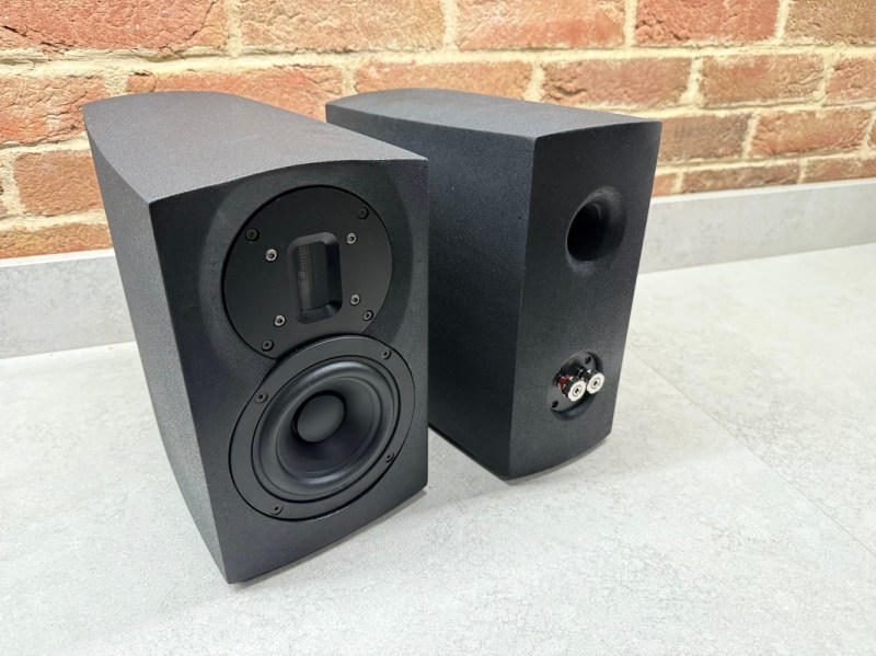
The bulk of the speakers were designed with OpenSCAD, with the parametric design allowing for easy adjustments to accommodate different drivers and enclosure volumes. A number of the panels of the speakers are curved as well, which is more difficult with traditional speaker materials like MDF but much easier with this 3D printed design. There were a few hiccups along the way though; while the plastic used here is much denser than MDF, the amount of infill needed to be experimented with to achieve a good finish. The parametric design paid off here as well as the original didn’t fit exactly within the print bed, so without having to split up the print the speakers’ shape was slightly tweaked instead. In the end he has a finished set of speakers that look and sound like a high-end product.
There are a few other perks to a parametric design like this as well. [Cal] can take his design for smaller desk-based speakers and tweak a few dimensions and get a model designed to stand up on the floor instead. It’s a design process that adds a lot of options and although it takes a bit more up-front effort it can be worth it while prototyping or even for producing different products quickly. If you want to make something much larger than the print bed and slightly changing the design won’t cut it, [Cal] recently showed us how to easily print huge objects like arcade cabinets with fairly standard sized 3D printers.


What is wrong or right with “the amount of infill”? And what has the finish (surface) to do with infill?
If you have too thin walls, you will see some artifacts from too much overextruded infill.
Reading everything again, this may just be an misunderstanding:
“The density of MDF is around 500kg/m^3 versus PLA at around 1240kg/m^3. So this means I could print at 50% infill and exceed the density of MDF.
First I tried 90% infill. It did not go well. There was terrible curling with the default settings with the X1 carbon; unacceptable! I reduced to infill to 50% which helped – less plastic, less shrinkage in theory.
[…]
I took a look at the settings. As it turns out, the plate is called a “cool plate” for a reason! The default settings leave it at 35c, which is far less than the 60c I used to use with my old printer (a janky Anet A8).
”
So, modifying infill was just a trial to test bed adhesion, but it was not a right setting to tweak here. It DOESN’T have anything to do with surface finish in the original article.
My point being, the sentence above that Bryan has written is unclear at best and deserves editing.
I run an Anet A8 as well. Can confirm the lankiness!!
It happens that I run Anet A8 as well. I’ve printed some strengthening brackets, a cable chain thingy, replaced steppers, glued the frame after breaking it, even had to replace driver board with rearm+ramps due to me shorting some pins in one careless moment. It’s like the old jeep of 3d printers, not a lot out of original, but still going strong and printing in good quality. I even managed to print a voronoi bear on it pretty reliably. During covid printed some mask holders in petg too, was printing for two weeks almost non-stop.
While I recognize it’s not the most common use, “Finish” could be used here to also describe the end result of sound not just the end result of the the looks.
I’ve built a lot of speaker enclosures. In this particular application, one must be mindful of the material density and rigidity. Every material is different and in certain configurations certain frequencies can cause what I like to call “case resonance”. Under acoustic load you can get buzzes and “pops” from the case itself, sounding like a damaged or horribly tuned speaker. Infilled plastic has such a wide range of properties… testing must be done. The best way I have found is by touch, although a particulate on the surface can be used. You will see and feel it “jump” beyond the normal vibration of the case at the point of resonance. The goal is to build it so that the resonances are beyond the range of hearing, or at least the range of the speaker, pretty much. With woofers you can sometimes get second and third-order harmonics you need to watch for. That’s where a good crossover helps a lot.
Fixing it without a rebuild could include attaching weights to the interior of the surface, or reinforcing it with ribbing or other structural supplements; anything to change the way it moves.
I had the same thought concerning the plastic material. Having less infill creates cavities within the structure, which could create odd resonances.
While 3D printing speaker cabinets could have potential for highly specialized sound profiles, experimentation is going to be needed.b
I was wondering about those resonant cavities, too, and wondering if they might be used to some advantage. Not that I’m going to test it, but I would read about what somebody else finds if they specifically test for that. :-)
I wonder if those cavities should be of a wide variety of sizes, to avoid resonant frequencies.
The YouTuber DIY Perks published plans for 3D printed speakers, and he printed hollow walls that he then filled with plaster of paris mixed with PVA glue to give them density and reduce their ringing which seemed like an interesting approach.
I don’t know if ringing is the same as resonance, but I recently watched this youtube video regarding this:
“Mass and stiffness literarily do nothing to dampen resonance”
https://youtu.be/OQsVdGmOJx4?si=pgcD5z-QkoSB_COa&t=388
I was looking for that video to post here! I watched it not long ago as well. Very interesting stuff!
I was thinking something similar. It wouldn’t be so difficult to print it in parts and instead of infil use a wet concrete. I have no idea what the results will be with the quality of the sound. I did watch a video a while ago about this company making speaker housing from marble. It was some audiophile speaker company so I take everything they say with a bucket of salt. I know MDF is used because it’s so rigid but I’m not a speaker designer.
MDF is used for speaker cabinets because it is dense, heavier than most wood panels and less likely to resonate, easy to cut/mill/shape, easy to finish. And because it is CHEAP.
Myself, I wouldn’t consider 3-D printing a speaker cabinet for any but the smallest speakers.
MDF , by it’s very definition is not that dense, (Medium Density Fibreboard). There is HDF, or make it double skinned ,
and fill the gap with sand.
Going by advice I’ve seen from photographers for tripods: rigid materials may resist vibration, but they tend to transmit and reflect instead of absorb. So, tripods made of wood are heavy but valued. So MDF may also absorb vibrations.
There are companies that use concrete for loudspeakers. It’s nice and rigid, and doesn’t resonate.
On the DIY Perks YT channel, he prints speaker enclosures with hollow walls, which he then fills with plaster for mass and rigidity.
one of the tricks that can work in older homes, is to convert a brick chimney and fireplace, into a sub woofer enclosure….the need to
plug it at your calculated volume, does require some creative risk exposure on the roof, but it will give a solid thump.
if you want something more siezmic, filling speaker cones with lead shot and epoxy, and just bolting them to floors and walls is another option
Hexibase has an excellent video about this subject https://youtu.be/n3wlmaENJio
There was just a good YouTube video on this by PrintYourSpeakers. It covers the infill question pretty well with some decent analysis of different amounts of infill.
Forgot the link. https://youtu.be/OQsVdGmOJx4?si=xLwbcwuZiCtUAg1p
Interesting, I’ve found this one https://youtu.be/n3wlmaENJio
TIL about offset() in OpenSCAD. All this time I’ve been using minkowski() for making chamfers and edge radii.
If printing an enclosure in the unlimited freedom of 3D plastic why make flat sides parallel to boot? There was some seashell shaped speaker design here a few years ago. No flat resonate surfaces acting like drum heads and tapering dimensions to mess up internal standing waves at any one particular frequency are design goals, or in other words think out side of the box which is hard to do with wood. Conventional aesthetics have get out of the way here.
I remember shell shaped concrete speakers being all the rage back in mid nineties already. Ah yes 1993 Nautilus.