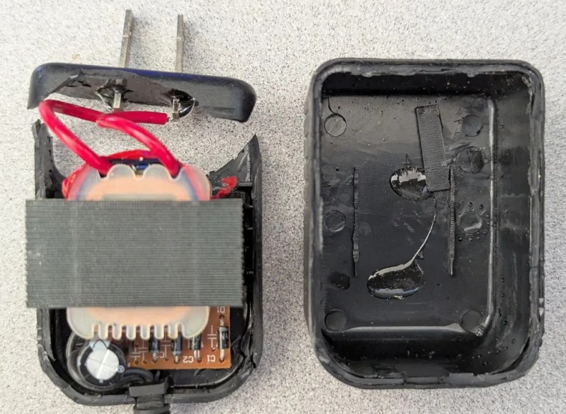
Getting a look at the internals of a garden variety “wall wart” isn’t the sort of thing that’s likely to excite the average Hackaday reader. You’ve probably cracked one open yourself, and even if you haven’t, you’ve likely got a pretty good idea of what’s inside that sealed up brick of plastic. But sometimes a teardown can be just as much about the journey as it is the end result.
Truth be told, we’re not 100% sure if this teardown from [Brian Dipert] over at EDN was meant as an April Fool’s joke or not. Certainly it was posted on the right day, but the style is close enough to some of his previous work that it’s hard to say. In any event, he’s created a visual feast — never in history has an AC/DC adapter been photographed so completely and tastefully.

[Brian] even goes so far as to include images of the 2.5 lb sledgehammer and paint scraper that he uses to brutally break open the ultrasonic-welded enclosure. The dichotomy between the thoughtful imagery and the savage way [Brian] breaks the device open only adds to the surreal nature of the piece. Truly, the whole thing seems like it should be part of some avant garde installation in SoHo.
After he’s presented more than 20 images of the exterior of the broken wall wart, [Brian] finally gets to looking at the internals. There’s really not much to look at, there’s a few circuit diagrams and an explanation of the theory behind these unregulated power supplies, and then the write-up comes to a close as abruptly as it started.
So does it raise the simple teardown to an art form? We’re not sure, but we know that we’ll never look at a power adapter in quite the same way again.


That article is most certainly a joke, and intended as a joke.
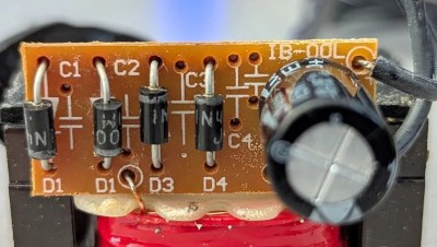
The capacitors missing from the PCB are most certainly not intended to form a voltage multiplier. Most likely they are there to reduce switching noise from the rectifier diodes. You wouldn’t put a voltage multiplier in a DC power supply. If you needed a higher voltage, you’d use a transformer with a higher output voltage.
Joke or not, I always enjoy a well-photographed teardown.
Whoo, that’s a fancy wall wart like we don’t make anymore.
4 diodes!? And what more, a FULL BRIDGE RECTIFIER!?
Modern wall wart only uses one diode and strap the other: it’s way cheaper.
Also, the capacitor seems too high quality for a modern one.
Eyup, definitely a high end garden variety wall wart.
I have cracked open my fair share of wall warts!
That’s where they hide the high-quality magnet wire.
April fools or not, you also almost never see this kind of big-iron wallwart these days — they are all godforsaken switching supplies.
More efficient, sure, but they are a huge broadband radiofrequency interference source, even the good ones. The cheap ones are truly a plague.
In a couple of switchersthat blew up, I found that the pcb has all the required filter component – holes.
If a reputable brand buys it, they presumably populate them. Otherwise – no filtering at all.
Have one, a big monster too.
D1, D1, D3, D4?
Fibbonacci designator numbering.
Good old days, not the exploding USB chargers.
Why, I took apart a wall wart just yesterday! It was an official Raspberry Pi one (in the interests of repeatability). Nothing interesting about it except that, for reasons unclear to me, the PCB was connected to the AC pins by a pair of long, non-removable, custom-shaped bare steel strips that run around the outside of the shell. I would be curious to know how that design came about.
You should post pictures
Mine’s now glued into its new form (a pi zero w print server wall wart), but you can see what I mean in a couple of the pictures on this page:
https://www.chargerlab.com/teardown-of-raspberry-pi-15w-usb-c-power-adapter-ksa-15e-051300hu/
(I was using the older model but it’s basically the same.)
Imagine different plugs used all over the world. so different strips, all mating the same two point on the pcb. you could use soldered wires, but i think this is fully automated assembly. At the most a human soldered the strips to the board
Can anyone tell me why electrolytic csps have that cross in the end face? Is it to create a weak point so they fail by oozing rather than exploding, or am I overthinking it?
Yes.