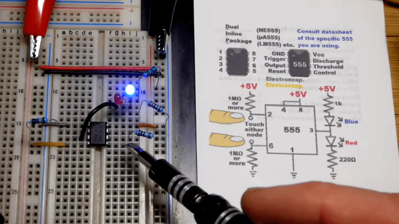
There seems to be nothing a 555 can’t do. We’ve seen it before, but [electronzapdotcom] reminds us you can use a 555 and a few parts to make a reasonable touch switch in this video, embedded below.
The circuit uses some very large resistors so that noise from your body can overcome the logic level on the trigger and threshold inputs. You can easily adapt this idea if you need a simple touch switch. Though we imagine this circuit wouldn’t work well if you were in a quiet environment. We suspect 50 or 60 Hz hum is coupling through your finger and triggering the pins, but it could be a different effect.
How reliable is it? Beats us. The circuit is a bistable, so essentially your finger pumps a signal into a flip-flop. This is old trick, but could be useful. Of course, if you really need a touch switch, you have plenty of options. You can get little modules. Or, directly measure skin resistance.


In b4 someone suggests you could have used a ‘555.
There are many revisions of the 555, I am sure someone will share an insight which 555 would have been better than this 555. Sadly not all 555 are born equal.
The Forrst Mims “Engineer’s Notebook” has a similar circuit on page 98:
https://ia600500.us.archive.org/8/items/EngineersNotebookIIAHandbook/Engineer%27s%20Notebook%20II%20A%20Handbook%20Of%20Integrated%20Circuit%20Applications%20-%20Forrest%20Mims_text.pdf
Mims says it “works best indoors due to stray AC field. Elsewhere, try touching pins 1 and 2.”
You could add a second 555 to oscillate and spread that stray AC field around the device.
Best Mims book. Highly recommended.
There is another similar schematic in the book “IC Timer Cookbook” by Walter Jung.
Using 555 is no longer politically correct, it MUST connect to the internet AND have OTA.
And 300 securities holes including a hard coded admin account.
555flex needs to die already. there are so many people flexing about doing cool stuff with it. and i get it. but, why, really? there are better way to do things. for this case, we have dedicated touch ICs that can do the job much better and cost nothing (in fact, thanks to arduino, you can even get the whole thing in a pcb)
you’re not really learning a useful skill by learning 555 tricks. it’s so rare that you’ll actually use it in real life, and if you do, it’s probably just going to be the basic circuits. because anything more complex you now need more than a 555 and for that matter you might as well just use a microcontroller.
example: i have a fridge, with an ince and water dispenser. my brother likes to get ice all the time, and everyone else has to push the WATER button again, or you get a surprise ice cube instead of water. so what I did was a circuit that tapped into the ICE LED, waited a minute, and pulled down the WATER button. I thought,…this is a slam dunk 555! and i looked it up quickly, gathered the components, noticed i needed also an output transistor, so i got a transistor too, and I started wiring it up, and i got a ratsnest of components that didn’t work and needed debugging, and it was finnicky too…
so i looked in the junkbox and found a PIC12F629. i implemented a small C program in 5 minutes. adjusted the delay, and it was working at first try. i didn’t need any external components, other than the decoupling capacitor. this thing can work open-collector, it has internal clock, draws a tiny amount of current. in the end, i regretted even trying to use a 555.
life’s too short for 555s
They’re occasionally useful as they have a wide voltage range (2v-18V), can handle a fair bit of current (200mA @ 0.5W) and best of all they tend to still work when you hook up the power backwards.
Yes there are infinitely better ways to do this with an MCU or even dedicated ICs. That’s not the point.
It’s about coaxing a 50 year old design into doing something its designers probably never imagined.
yes, that’s why i called it 555flex. it’s just flexing at this point.
I find it is the other way around. No need to find your programmer. Finding out your programmer’s software isn’t cooperating. Needing another power supply voltage for your timer or oscillator.
Ah triple 5, remind me olden days.