Sick of raiding old TVs and CRT monitors for flyback transformers to feed your high-voltage addiction? Never fear; if you’re careful, a 3D-printed flyback might be just the thing you’re looking for.
To be fair, it’s pretty easy to come by new flyback transformers, so building your own isn’t strictly necessary. But [SciTubeHD] was in the market for a particularly large flyback, in a good-natured effort to displace [Jay Bowles] from his lofty perch atop the flyback heap. And it’s also true that this project isn’t entirely 3D-printed, as the split core of the transformer was sourced commercially. The secondary coil, though, was where most of the effort went, with a secondary form made from multiple snap-together discs epoxied together for good measure. The secondary has about a kilometer of 30-gauge magnet wire while the primary holds just ten turns of 8-gauge wire covered with silicone high-voltage insulation.
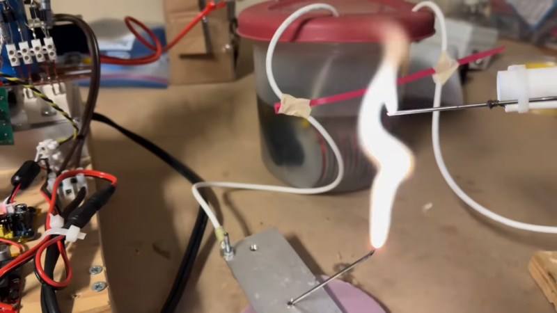
To decrease the likelihood of arcing, the transformer was placed in a plastic container filled with enough mineral oil liquid dielectric to cover the secondary. After degassing in a vacuum chamber for a day, [SciTubeHD] hooked the primary to a couple of different but equally formidable-looking full-bridge inverters for testing. The coil was capable of some pretty spicy arcs — [SciTubeHD] measured 20 amps draw at 35 volts AC input, so this thing isn’t to be trifled with. STL files for the core parts are coming up soon; we trust schematics for the power supply will be available, too.


High voltage is very dangerous and there is a risk of death when touching. You’re better off using it remotly from behind a blast shield.
Also, keep it away from your nuclear weapons.
Well then don’t touch it then.
I’m sick and tired not finding replacement flybacks when an old CRT TV or monitor shuffles its mortal coil. And almost every one of them uses a different model flyback. By the late 70s, CRTs tend to outlive most electronics in the chassis, so the flyback is the #1 hard part to replace now.
(and btw, yes I know I’m totally missing the point here.)
I don’t know if you are entirely missing the point here.
I could see a project like this getting some open source expansion to a parametric version. If some of the analog gurus pitch in their knowledge, then I’m certain this could get boiled down to a single OpenSCAD/FreeCAD file that you just slap in your voltages, currents and frequencies and get a model spat out. With a bonus if it can automatically give you stats for the wire to use (assuming it needs to change for some size combinations), and if it can use fixed size cores that could be made from hardware store ingredients.
If this went that direction than you’d be able to solve your missing flyback problem with a 3D printer and some handiwork.
Yep! Im with this! I dont see anything similar on the web, we need to start from almost 0 🥲
Is it really a flyback transformer if it isn’t designed to provide power to cause a CRT beam to fly back at the end of a raster?
My first high voltage generator was a Ford model T ignition coil, it worked on the same principle.
yes, because it refers to how it works, not how it is used
I am in awe of people who have the knowledge and skills to work with such voltages safely and I am not qualified to ascertain the safety of his setup. I must say that the demonstration at the 8:30 mark which heats the arc tips sufficiently to sputter sparks all over the place including the power supply is triggering my fear reflex.
Probably a very stupid question:
In theory could a pair of 200 mm x 10 mm Mn-Zn ferrite rods to generate a 500kV arc ?
Like 500kV in dry air at sea level pressure should be able to arc 167 mm.
(ref: https://hackaday.com/2016/12/08/measuring-high-voltage-in-millimeters-and-other-hv-probe-tricks/ ).
Would a Mn-Zn ferrite rod of 10 mm diameter be too small for a Tesla style of coil winding ? Or would you need to use really fine gauge wire for the secondary/arc winding and segment many individual flat spiral coils.