Trackside Observations Of A Rail Power Enthusiast

The life of a Hackaday writer often involves hours spent at a computer searching for all the cool hacks you love, but its perks come in not being tied to an office, and in periodically traveling around our community’s spaces. This suits me perfectly, because as well as having an all-consuming interest in technology, I am a lifelong rail enthusiast. I am rarely without an Interrail pass, and for me Europe’s railways serve as both comfortable mobile office space and a relatively stress free way to cover distance compared to the hell of security theatre at the airport. Along the way I find myself looking at the infrastructure which passes my window, and I have become increasingly fascinated with the power systems behind electric railways. There are so many different voltage and distribution standards as you cross the continent, so just how are they all accommodated? This deserves a closer look.

So Many Different Ways To Power A Train

A British Rail Class 165 "Networker" train at a platform on Marylebone station, London.
Diesel trains like this one are for the dinosaurs.

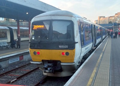
In Europe where this is being written, the majority of main line railways run on electric power, as do many subsidiary routes. It’s not universal, for example my stomping ground in north Oxfordshire is still served by diesel trains, but in most cases if you take a long train journey it will be powered by electricity. This is a trend reflected in many other countries with large railway networks, except sadly for the United States, which has electrified only a small proportion of its huge network.

Of those many distribution standards there are two main groups when it comes to trackside, those with an overhead wire from which the train takes its power by a pantograph on its roof, or those with a third rail on which the train uses a sliding contact shoe. It’s more usual to see third rails in use on suburban and metro services, but if you take a trip to Southern England you’ll find third rail electric long distance express services. There are even four-rail systems such as the London Underground, where the fourth rail serves as an insulated return conductor to prevent electrolytic corrosion in the cast-iron tunnel linings. Continue reading “Trackside Observations Of A Rail Power Enthusiast”

Studying QR Code Degradation

It’s fair to say that QR codes are a technology that has finally come of age. A decade or more ago they were a little over-hyped and sometimes used in inappropriate or pointless ways, but now they are an accepted and useful part of life.

They’re not without their faults though, one of which is that despite four increasingly redundant levels of error correction, there comes a point at which a degraded QR code can no longer be read. [HumanQR] is soliciting these broken QR codes for research purposes and inclusion in an eventual open-source database, and they’ll even have a shot at repairing your submissions for you.

It’s a problem inherent to all digital media, that once the limit of whatever error correction they contain has been reached, they arrive at a cliff-edge at which they go immediately from readability to non readability. The example given in the linked article is a locator tag on a stray cat, it had been rubbed away in part. Improving its contrast, sharply defining its edges, and improving the definition of its fiducials was able to revive it, we hope leading to the cat being returned home.

The idea is that by studying enough damaged codes it should be possible to identify the means by which they become degraded, and perhaps come up with a way to inform some repair software. Meanwhile if you are interested, you might want to learn more about how they work, the hard way.

Simulating High-Side Bootstrap Circuits With LTSpice

LTSpice is a tool that every electronics nerd should have at least a basic knowledge of. Those of us who work professionally in the analog and power worlds rely heavily on the validity of our simulations. It’s one of the basic skills taught at college, and essential to truly understand how a circuit behaves. [Mano] has quite a collection of videos about the tool, and here is a great video explanation of how a bootstrap circuit works, enabling a high-side driver to work in the context of driving a simple buck converter. However, before understanding what a bootstrap is, we need to talk a little theory.

Bootstrap circuits are very common when NMOS (or NPN) devices are used on the high side of a switching circuit, such as a half-bridge (and by extension, a full bridge) used to drive a motor or pump current into a power supply.

A simple half-bridge driving illustrates the high-side NMOS driving problem.

From a simplistic viewpoint, due to the apparent symmetry, you’d want to have an NMOS device at the bottom and expect a PMOS device to be at the top. However, PMOS and PNP devices are weaker, rarer and more expensive than NMOS, which is all down to the device physics; simply put, the hole mobility in silicon and most other semiconductors is much lower than the electron mobility, which results in much less current. Hence, NMOS and NPN are predominant in power circuits.

As some will be aware, to drive a high-side switching transistor, such as an NPN bipolar or an NMOS device, the source end will not be at ground, but will be tied to the switching node, which for a power supply is the output voltage. You need a way to drive the gate voltage in excess of the source or emitter end by at least the threshold voltage. This is necessary to get the device to fully turn on, to give the lowest resistance, and to cause the least power dissipation. But how do you get from the logic-level PWM control waveform to what the gate needs to switch correctly?

The answer is to use a so-called bootstrap capacitor. The idea is simple enough: during one half of the driving waveform, the capacitor is charged to some fixed voltage with respect to ground, since one end of the capacitor will be grounded periodically. On the other half cycle, the previously grounded end, jumps up to the output voltage (the source end of the high side transistor) which boosts the other side of the capacitor in excess of the source (because it got charged already) providing a temporary high-voltage floating supply than can be used to drive the high-side gate, and reliably switch on the transistor. [Mano] explains it much better in a practical scenario in the video below, but now you get the why and how of the technique.

We see videos about LTSpice quite a bit, like this excellent YouTube resource by [FesZ] for starters.

Continue reading “Simulating High-Side Bootstrap Circuits With LTSpice”