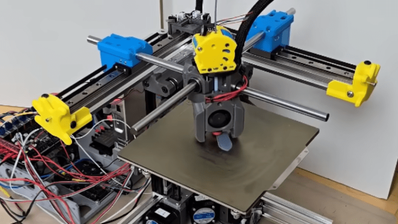
If you’re looking for a more open, unenclosed 3D printer design than a cubic frame can accommodate, but don’t want to use a bed-slinger, you don’t have many options. [Boothy Builds] recently found himself in this situation, so he designed the Hi5, a printer that holds its hotend between two cantilevered arms.
The hotend uses bearings to slide along the metal arms, which themselves run along linear rails. The most difficult part of the design was creating the coupling between the guides that slides along the arms. It had to be rigid enough to position the hotend accurately and repeatably, but also flexible enough avoid binding. The current design uses springs to tension the bearings, though [Boothy Builds] eventually intends to find a more elegant solution. Three independent rails support the print bed, which lets the printer make small alterations to the bed’s tilt, automatically tramming it. Earlier iterations used CNC-milled bed supports, but [Boothy Builds] found that 3D printed plastic supports did a better job of damping out vibrations.
[Boothy Builds] notes that the current design puts the X and Y belts under considerable load, which sometimes causes them to slip, leading to occasional layer shifts and noise in the print. He acknowledges that the design still has room for improvement, but the design seems quite promising to us.
This printer’s use of cantilevered arms to support the print head puts it in good company with another interesting printer we’ve seen. Of course, that design element does also lend itself to the very cheapest of printers.
Thanks to [Keith Olson] for the tip!


It is great that people try new designs still. Kudos for a nice build and optimization process.
I agree, it looks less cluttered and light, but is it really? I’m not sure if anything is saved in parts or size compared to a core-x-y, maybe a shorter belt and two rollers?
But I would expect that printing on the far end comes with lower accuracy and more artifacts due to stability. Non uniformity across the print bed is an annoying limitation.
Well, someone had to graduate from the “We know it’s not a great idea but we’ll do it anyway” school of thinking.
I built a canteleaver printer with all linear rails, no sag at the ends. I did have to make sure that the vertical rail was solidly attached to the base as the plastic printed parts weren’t up to the job.
SCARA geometry might give more rigidity, though it doesn’t seem to be particularly popular for 3D printers. Probably for some good reason that I don’t know.
SCARA robots working in XYZ mode require very advanced mathematics to control, something that needs a very powerful CPU, not $2 ARM microcontroller.
What about a raspberry pi 4 or 5?
Is it really any more complicated than e.g. delta robots that were quite popular a decade ago?
I think Smoothieware has or at least planned scara support.
The kinematics are solve with 2 trigonometric equations, and you can do it fairly fast on you typical 3D printer controller board. Both Marlin and RepRap firmware support SCARA kinematics out the box. Dynamics of the system will be more complicated to deal with. But before even getting there, they a harder to calibrated and diagnose for if they are not setup fully right.
what about a printer using peaucellier lipkin linkage. that would make the scara math easier since you only need to solve for one axis instead of two, plus no need for expensive guide rails.
The math is only difficult when it’s initially derived and proven. Then it’s just an algorithm, and a not-terribly-work-difficult-one. That’s how math works. And that’s what microcontrollers are made for.
It isn’t that bad, really the only downside is SCARA work on polar co-ordinates at the hardware level, so to make best use of them you probably want to be slicing in a polar focused way as well – to cut out all the varied accelerations trying to draw straight lines in places it doesn’t matter, keep the movements as minimal as required, and adapting the print file so the surface speed is consistent or vary the extrusion rate when in the bed areas the traverse is slower/faster etc
Also has to be said these days that cheap micro driving most printers would be very able to do what works out as pretty basic trig functions for positioning, and if your micro really is too slow to convert x-y co-ordinate g-code output by the slicer into the polar movements required on the fly (which I actually doubt would be the case for any modern controller) it can always reprocess that sliced file entirely in advance…
A bit of similarity to the Ultimaker motion system. Not sure why there should be a belt tension issue, though. I’m also unsure of why the Z axis needs to be so complex. Once you manually level a bed, it usually doesn’t need much tweaking thereafter.
A bit, but not the same. And I think a critical difference is that the belts here cause the sliders on the linear reals to be pulled skew, causing needless extra friction. Putting the belt above/below the rail would help here.
I think those are also NEMA14 motors, we use NEMA17 at Ultimaker, as just putting some more power behind that is worth it for reliability.
wow really going the opposite direction of anything i’ve ever wanted out of a 3d printer…mechanically it gives me the icks, just because i know it’s gonna flex like mad. definitely a work of art though :)
imo this could be paired with closed loop control. “something” should be measuring the actual location of the print head, and then you can compensate for flex. and you might actually get a better result out of this ridiculous design than established ones that are open-loop control.
the thing is, every printer flexes a little bit and would benefit from closed loop. especially as people push the limits of movement. a lot of details to get right but i look forward to finding out what printers look like after the control revolution