
When Raspberry Pi’s new RP2350 MCU was released in 2024, it had a slight issue in that its GPIO pins would leak a significant amount of current when a pin is configured as input with the input buffer enabled. Known as erratum 9 (E9), it has now been addressed per the July 29 Product Change Note from Raspberry Pi for the A4 stepping along with a host of other hardware and software issues.
Although the PCN is for stepping A4, it covers both steppings A3 and A4, with the hardware fixes in A3 and only software (bootrom) fixes present in A4, as confirmed by the updated RP2350 datasheet. It tells us that A3 was an internal development stepping, ergo we should only be seeing the A4 stepping in the wild alongside the original defective A2 stepping.
When we first reported on the E9 bug it was still quite unclear what this issue was about, but nearly a month later it was officially defined as an input mode current leakage issue due to an internal pull-up that was too weak. This silicon-level issue has now finally been addressed in the A3 and thus new public A4 stepping.
Although we still have to see whether this is the end of the E9 saga, this should at least offer a way forward to those who wish to use the RP2350 MCU, but who were balking at the workarounds required for E9 such as external pull-downs.


They’re using the remaining A3 chips on Pico 2 boards, but only A4 chips will be available as parts. The hardware errata are fixed on both, A4 just has bootrom changes to close some of the vulnerabilities the hacking challenge revealed.
The reasoning is likely that people buying Picos aren’t the businesses who’d care about security. Businesses would be buying the singular RP235x chip, not Picos.
“Identification Method to Distinguish Change
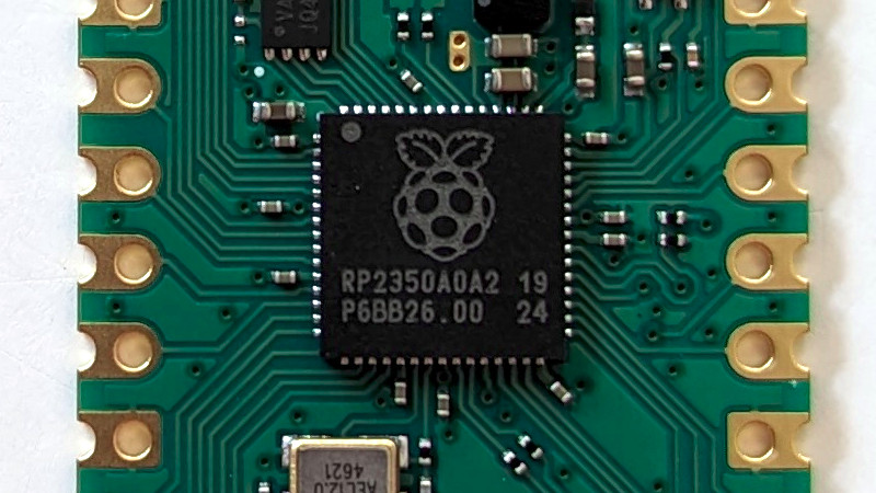
The new product can be distinguished by examination of the chip. ”
This is an important change. And then they do not document a proper way to tell the steppings apart in software?
I guess it could be done by reading out the bootrom git tag and comparing it to some not yet known values, but not properly documenting this is not a good idea.
“Software running on the device can also read the CHIP_ID.REVISION register field, or call the rp2350_chip_version() SDK function.”
For those of us confused by the term ‘stepping’, courtesy of my friendly online AI: Chip stepping refers to the versioning system used by manufacturers to track revisions and improvements made to a microprocessor during its lifecycle. Each stepping indicates changes such as bug fixes, performance enhancements, or adjustments in manufacturing processes, typically represented by a combination of letters and numbers.
It’s basically the semiconductor equivalent of a revision.
Often meant to fix bugs/issues and/or to increase production yield or otherwise lower production costs.
And for those curious why it’s called stepping:
Source: https://en.wikipedia.org/wiki/Stepping_level
Source: https://en.wikipedia.org/wiki/Stepper
i am glad that the pico line is progressing beyond this problem.
but imo the biggest problem was the extremely poor communication around this issue. attempts to deny, hide, and then minimize the problem did no favors to anyone. and so i am rather adamant that this is not a mere nit: “an input mode current leakage issue due to an internal pull-up that was too weak”. that clause is harmful to the community. if you don’t understand the problem well enough to write about it then please don’t write about it!
a stronger pull-up could partially mask the problem in some conditions simply by wasting the current that was being leaked. the strength or weakness of the pull-ups did not have any causative role at all. at this day, especially when it was hackaday that brought to my attention the actual description of the problem, there is no excuse for further spreading the initial misinformation that raspberry used to try to obfuscate the problem in the first place!
So much this. It was not about pullups/down. The most basic high impedance state was not there / working.
That’s not right, putting pins into high impedance mode has always worked just fine. E9 would only happen when you also have the input buffer enabled and the voltage is in the undefined region, i.e. you’re trying to read a digital signal that’s transitioning from high to low or the other way around.
Yeah, in other words, if you have a GPIO and you try to set it HiZ to use as a input, it misbehaves unless the source has enough drive to overcome the input leakage.
Yes, you can disconnect the input entirely, but generally if you say “HiZ” I’m thinking “set a digital input to high impedance” and that broke with that errata.
Seems like a cocktail of them being caught blindsided by a pretty serious albeit kinda sorta edge-case HW bug that slipped through their internal testing procedures, not wanting to be stuck with inventory since people can easily go into a fearmongering spiral on social media, even if they’re clear and up-front about explaining it even to the average Joe and Jane (basically a variant of the Osborne Effect) , and lastly that they didn’t have any experience dealing with such type of issues (closest being the power regulator on rPi 2 boards resetting the system when exposed to sudden sharp light like a camera flash).
Keep in mind, I’m not excusing their behavior, rather explaining the supposed rationale as I observed it.
I don’t get this take. It took a few weeks for them to do an internal investigation before they came out with an official statement, which correctly diagnosed the issue (rpi never said it was a “too weak pull up resistor!”, but there were various incorrect hypotheses floated by users trying to isolate the problem in the early days.)
It really sounds like you’re blaming them for your own distorted view of the events of the time.
No, they put out errata before the full details, and those errata were incomplete. They put out an incomplete errata for E9 that got expanded on. The whole interaction chain was:
https://github.com/raspberrypi/pico-feedback/issues/401
The initial E9 errata was much different than an input leakage issue.
That makes the complaint even more dumb. So not only did the engineers get started investigating right away, and provided interim responses during the process, they updated the errata repeatedly until it was fully correct.
Criticising a company for not instantaneously providing a perfect response is offensive, and the armchair dingbats doing it should be ashamed.
Don’t agree. Incomplete errata should be marked as “incomplete and under investigation, other issues may arise” or similar. You basically have to make sure people understand using the chip might be a total risk, because no workaround was possible.
The timeframe of the whole thing was less than 2 weeks.
I challenge any of the people who are still whining about it to show how they were directly impacted by that not being shorter.
“It really sounds like you’re blaming them for your own distorted view of the events of the time.”
yes, that is precisely what i’m doing. a decent test of the effectiveness of communication is the impact it has on the consumer. in order to communicate well with the community, they have to foster correct ideas within that community. if the community is widely misinformed then they have failed this central role they must fill for the community.
it’s possible to fail at this for reasons outside your control. but this one is all unforced errors, from my perspective.
when it was first discovered, it was easy to characterize the defect. but they refused to do so until after they had ruled out a simple fix. their hope was to avoid ever admitting what a serious defect it is, by having the fix in hand before anyone knows the defect exists.
after they admitted there was no easy work-around if you actually want high-impedance inputs (the sine qua non of embedded GPIO, imo), they still were hesitant to disclose this issue. to this day, adafruit discloses on their product page for rp2350 products that it has the erratum, while the raspberrypi.com store’s product page does not. adafruit does this because they want to help their community, and raspberrypi makes the different choice because of their different attitude towards that same community. it is really very stark.
i’m so upset about it because i think the rp2040 / rp2350 product line is brilliant. even with such an error, it does not deserve to have this antagonism against its community!
This is an amateur take. Most complex chips have long errata lists. Playing Karen and demanding the management to take better action than what they have done is delusional.
The launch datasheet had an errata entry that explained what happens and when. It didn’t explain the mechanism behind it, because at that point we had only speculation on the mechanism. That information followed once we’d had more time to follow up internally and with the pad vendor.
We’d already speculated at that time that leakage through the input buffer was a potential cause. We also had other explanations that aligned with most of the facts, including input buffer enable being a prerequisite, and those turned out to be incorrect. I wrote the launch version of the E9 errata write-up and I am certain we made the correct call on what to include (facts about behaviour) and what not to include (speculation on the mechanism).
Exactly which part of “documented in the datasheet on day one” is trying to hide the issue?
The early errata in the datasheet did not cover what happened: it wasn’t clear until the full errata came out. There’s a GitHub issue linked above which specifically pointed this out.
You keep insisting that the Pico engineering team somehow magically knew all the real details before they’d even finished investigating it and were just hiding it from everyone.
They’re not the ones acting in bad faith.
There’s a point here that’s probably not appreciated unless you work in semiconductors .. the issue occured inside a circuit not designed by RPi themselves, i.e. the I/O pad. These issues can be difficult to simulate, debug and fix because usually the pad vendor will not allow the user to inspect the exact details of the circuit (though if you’re an engineer there are some ways round that). If you’re a tiny design company it can be almost impossible to get the attention of the vendor (been there, done that); I suspect that RPi have a bit more more influence given their public profile.
So I agree that RPi seems to have done all they can to be upfront about this. If there was a period of confusion between first acknowledgement and final erratum, then this is due to their willingness to acknowledge early on. In hindsight it might be better to just say .. “there seems to be an issue, we’re investigating” at first.
Nice to see that they’re fixing the problems of course. Unfortunately for us simple end users who are buying arduinos in random web shops things don’t look great, because usually the only way to find out the stepping is to buy, wait a month or so for delivery, then find out that it’s not what you wanted.
BTW, are there any more or less standard boards that utilise the larger chips and make available all 48 GPIO pins?
ugh that would be a nuissance for sure, to wait and see which stepping you get. but i checked on adafruit and both the adafruit rp2350 boards (like “feather”) and the official raspberry board “pico 2” have a footer on the ad “Please note: The Adafruit Feather RP2350 HSTX comes with the A2 version of the RP2350, which is affected by the E9 erratum.” hopefully they keep that up to date :)
so i’m optimistic the better vendors will do the right thing. that’s specifically the thing i love about rp2040 / pico, it’s only $4 ($5 for pico 2) even on reputable vendors like adafruit and sparkfun so there isn’t so much incentive to go on the ebay / aliexpress sort of markets. i’m a big fan of pico, a big step up over the stm32 boards i’ve used.
https://www.olimex.com/Products/RaspberryPi/PICO/PICO2-XXL/
thanks!
Also the Pimoroni pga2350 https://shop.pimoroni.com/products/pga2350?variant=42092629229651, although note that you have to supply your own USB connector of you need USB
I hear also that this new version is 5V tolerant on the GPIOs, very nice. Also… it would be great if they’d start making TQFP (0.8mm) and/or TSSOP (0.5mm) and/or SOIC (1.27mm) versions, much easier to solder on to your own board designs.
No, all the chips are officially 5v tolerant, even the original stepping. All they did is the extra qualification testing so that they could officially claim the feature in the specification.
Leadless (QFN/etc) are way easier to solder than QFP parts, you just need hot air. QFPs can be way worse because they won’t self align nearly as well.
I’ll grant that SOICs are the easiest, but I’d probably take QFNs over SSOPs, too.