When you think about highly-precise actuators, stepper motors probably aren’t the first device that comes to mind. However, as [Diffraction Limited]’s sub-micron capable micro-manipulator shows, they can reach extremely fine precision when paired with external feedback.
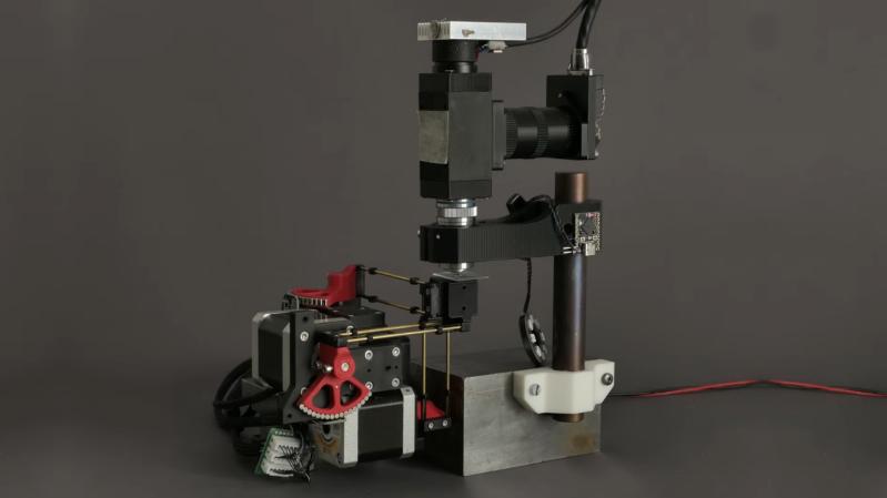
The micro-manipulator is made of a mobile platform supported by three pairs of parallel linkages, each linkage actuated by a crank mounted on a stepper motor. Rather than attaching to the structure with the more common flexures, these linkages swivel on ball joints. To minimize the effects of friction, the linkage bars are very long compared to the balls, and the wide range of allowed angles lets the manipulator’s stage move 23 mm in each direction.
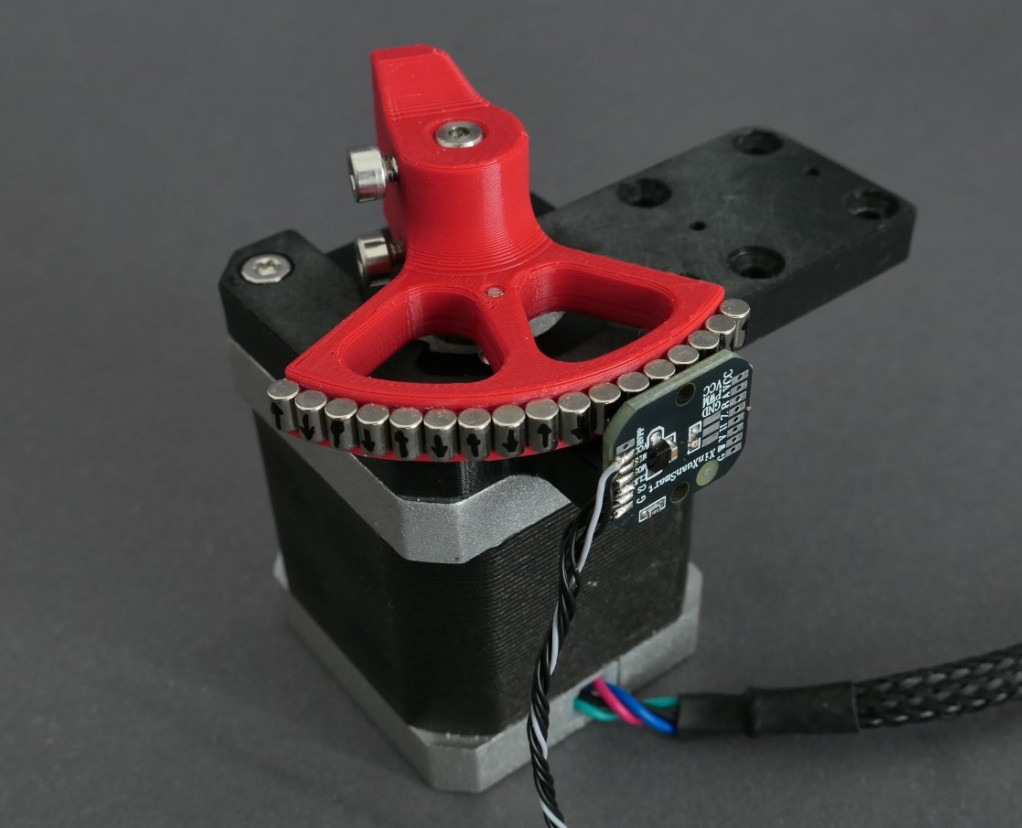 To have precision as well as range, the stepper motors needed closed-loop control, which a magnetic rotary encoder provides. The encoder can divide a single rotation of a magnet into 100,000 steps, but this wasn’t enough for [Diffraction Limited]; to increase its resolution, he attached an array of alternating-polarity magnets to the rotor and positioned the magnetic encoder near these. As the rotor turns, the encoder’s local magnetic field rotates rapidly, creating a kind of magnetic gear.
A Raspberry Pi Pico 2 and three motor drivers control this creation; even here, the attention to detail is impressive. The motor drivers couldn’t have internal charge pumps or clocked logic units, since these introduce tiny timing errors and motion jitter. The carrier circuit board is double-sided and uses through-hole components for ease of replication; in a nice touch, the lower silkscreen displays pin numbers.
To test the manipulator’s capabilities, [Diffraction Limited] used it to position a chip die under a microscope. To test its accuracy and repeatability, he traced the path a slicer generated for the first layer of a Benchy, vastly scaled-down, with the manipulator. When run slowly to reduce thermal drift, it could trace a Benchy within a 20-micrometer square, and had a resolution of about 50 nanometers.
He’s already used the micro-manipulator to couple an optical fiber with a laser, but [Diffraction Limited] has some other uses in mind, including maskless lithography (perhaps putting the stepper in “wafer stepper”), electrochemical 3D printing, focus stacking, and micromachining. For another promising take on small-scale manufacturing, check out the RepRapMicron.
Thanks to [Nik282000] for the tip!


I watched this video the other day. Such a cool and impressive design!
More
https://phys.org/news/2025-09-3d-micro-ion-quantum-tech.html
Super cool! Amazing!
Also very well made video.
What I’d love to see is someone putting my print head from RepRapMicron on this thing.
Note that Diffraction Limited is running into thermal expansion problems. The concept of RepRapMicron is to print a mm-sized printer which will reduce those issues as there’s simply less material to expand. That’s why it’s 3D printed, to prototype the process while simultaneously developing the tool needed.
It would probably be faster and more accurate to use Diffraction Limited’s printer to do the actual printing of the mm-sized device though, now that it is available. The sum of these projects would be greater than the two parts.
Absolutely stunning quality. Both of the project, and the video. This guy is on another level.
Fine in theory, but the magnets aren’t controlled for field strength or shape, and they have a lot of variability, so the exact field orientation between any two depends, and the precision becomes an illusion – not uniform or linear across the entire travel. It’s like a ruler that is accurate and precise over a couple millimeters at one point, and completely wild elsewhere.
Unless you characterize them and control for that. Would be pretty simple i think to run a characterization routine to find the exact step length with your particular magnets.
I agreed about the variability of the magnets at first thought, but after thinking about it more I think it can work accurately and precisely.
-The magnet diameters are probably actually pretty uniform, and that can be ensured by measuring and grouping magnets by diameter during assembly. This means that the pitch of the magnets (and their poles) chained together will be uniform and stay uniform.
-This leaves only the variation in the magnetics’ strength, which definitely will cause inaccurate interpolation if not mitigated for. However, it could easily be corrected for by calibrating & characterizing.
In the precision robotics world, optical encoders are the go-to. They utilize a disc that has tracks of millions of radial tick marks etched in with an ultra-fine laser. This can then be interpolated further by a factor of ~1,000X – resulting in position feedback accuracy being orders of magnitude more precise and accurate than other causes of inaccuracy, when you get down to this level of precision. But optical encoders also generally need to be characterized together with the controller to ensure full performance.
I meant the shape of the magnetic field. It doesn’t necessarily align with the physical shape of the magnet. This is because the magnet was not precisely aligned when it was made. It’s not a perfect ideal bar magnet.
They can be made very uniformly, but magnets from the usual sources probably aren’t. For instance, all you have to do is to snap two neodymium magnets together, and the mechanical shock will cause some re-orientation of the field.
Then there’s temperature variation, and also variation due to other metals around. The magnets don’t work in isolation – the entire magnet array forms a larger field, which couples with the iron body of the stepper motor, which changes the field orientation at the sensor depending on where the other magnets are. There are a lot of details that you have to account for in order to call this accurate.
I mean, there’s stories about people getting lost at sea because they tried to navigate in a fog and the iron anchor of the boat was stashed under the seat of the person holding the compass. You’d think it doesn’t make much of a difference, but when you’re trying to measure nanometer precision, every little bit counts.
Yeah, this is definitely a case of sub-micron resolution, but not sub-micron accuracy or even repeatability. Thermal drift and external magnetic fields will affect it.
Do you think that would be possible to calibrate that somehow?
For example if you use the micromanipulator as a microscope stage, at high magnification you can detect very fine motion with some computer vision (IIRC this is how he determined the precision of the stage at the end of the video). So I guess you can use that to determine the variations in the field strength and calibrate the motion to compensate for it?
Not sure if such calibrations would hold.
The video states at the beginning that the resolution they achieved is not absolute accuracy. Even the original encoder has errors from linearity and magnet positioning much greater than 1 LSB.
In fact it’s a perfect example of the difference between the two concepts.
Not “in theory”, in practice. [Diffraction Limited] actually built it and tested it. I don’t know why you’re speaking in hypotheticals when the video is right there.
When I saw it I kind of grimaced at the magnets and how variable they are and change with time. I recalled the old Inductosyn rotary encoders. I have often wondered why there isn’t good DIY version now. PCBs could make the “linear coil” wheels. I have been occasionally pondering the idea for telescope mounts since the 1970’s :-) There are single chips of the chip-under-epoxy-blob variety for doing something similar for cheap calipers and the angle measuring tools. I have not been able to find the source, but I have not dissolved a blob to see what the chip says.
Nothing is 100% precise, which is why he demonstrated the amount of actual variance at the tool head to quantify the tolerance. 50nm is pretty tight.
Disappointed I didn’t get credit for the tip since I posted it in #submit-a-tip on Hackaday Discord on 9/1 and didn’t see anybody else post it.
Yes, I’ve noticed that the credits seem intermittent as well after I sent in a published tip.
Using a “dumb” part, like the TB6612FNG, with a fast micro, seems pretty cool. Datasheet allows for a max PWM frequency of 100KHz.
Yes, very cool…
The silly bigger question for me is why is Diffraction Limited sponsoring this video.. for those of us in the astronomy realm of things, the Difraction limited create software, or used to, for imaging… Maybe this is what they do now. Kind of like Coors making pottery if you ask me.
Interesting in any case. But hey, what the hell.
In this case it’s the name of a DIY science Youtube channel and not a company.