How hard can it be to create your own inductors? Get a wire. Coil it up. Right? Well, the devil is definitely in the details, and [Nick] wants to share his ten tips for building “the perfect” inductor. We don’t know about perfect, but we do think he brings up some very good points. Check out his video below.
If you are winding wire around your finger (or, as it appears in the video, a fork) or you are using a beefy ferrite core, you’ll find something interesting in the video.
Of course, the issue with inductors is that wires aren’t perfect, nor are core materials. Factors like this lead to inefficiency and loss, sometimes in a frequency-dependent way.
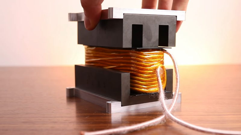
It looks like [Nick] is building a large switching power supply, so the subject inductor is a handful. He demonstrates some useful computational tools for analyzing data about cores, for example.
We learned a lot watching the tricks, but we were more interested in the inductor’s construction. We have to admit that the computed inductance of the coil matched quite closely to the measured value.
Need a variable inductor? No problem. Before ferrite cores, good coils were a lot harder to wind.


Exciting! I’ll have a watch when i get time! Inductors have been the Achilles heel in my toolbox for quite some time, i hope that changed
This takes me back to the time when I was tasked with designing a current supply to drive a very weird and cantankerous negative-resistance load, with output varying smoothly from 10mA at 2000V up to 2A at 400V. My design was basically a boost converter, but with an output transformer that had eight isolated secondary windings, each winding tailored to work over a portion of the output range. The nominal voltages of the windings were 800, 800, 400, 200, 100, 50, 25, and 12.5V. This was followed by logic that switched the different windings in and out as necessary, so that the available voltage was never more than 12.5V greater than what was required to maintain the desired current. Finally, there was a conventional linear regulator whose job was to take up the 0-12.5V slack between the transformer output voltage and whatever was required.
The transformer was a large ferrite pot core (the largest I could find at the time, in fact), and squeezing all of the windings into it while maintaining isolation was a challenge. I became well versed in the dielectric properties of extremely thin mylar tape. I also had to design some custom-machined HDPE bobbins to hold the windings.
Somewhat surprisingly, it all worked fine.
He stole his microphone from “notanengineer”. For the rest, I stopped the video after 70s, because I’m a bit allergic to background “music”.
I don’t know who [notanengineer] stole it from, but I’ve seen that gag floating around before him. It’s a funny bit, though. :)
Ive alwys gone by simple ratios nd common sense. Need 12V AC? 10 :1. Need to make a simple inverter with 10 pk-pk with 5V supply? 2:1. Common sense sys you cant have super short wire (short) or too long a wire, and its got to be big enough to carry the current.
Has served me well over the years. Yep, not perfect, but never really had any problems. Frequency maybe, but not an “issue”.
Oh yeah, and on a current transformer, the output will (WILL) try to drive whatever current it is designed for, that means an open circuit output “could” go to very high voltages trying to get there. Gotta have a load.