Over a year ago, we took a look at importing a .step file of a KiCad PCB into FreeCAD, then placing a sketch and extruding it. It was a small step, but I know it’s enough for most of you all, and that brings me joy. Today, we continue building a case for that PCB – the delay is because I stopped my USB-C work for a fair bit, and lost interest in the case accordingly, but I’m reviving it now.
Since then, FreeCAD has seen its v 1.0 release come to fruition, in particular getting a fair bit of work done to alleviate one of major problems for CAD packages, the “topological naming problem”; we will talk about it later on. The good news is, none of my tutorial appears to have been invalidated by version 1.0 changes. Another good news: since version 1.0, FreeCAD has definitely become a fair bit more stable, and that’s not even including some much-needed major features.
High time to pick the work back up, then! Let’s take a look at what’s in store for today: finishing the case in just a few more extrusions, explaining a few FreeCAD failure modes you might encounter, and giving some advice on how to make FreeCAD for you with minimum effort from your side.
As I explained in the last article, I do my FreeCAD work in the Part workbench, which is perfectly fine for this kind of model, and it doesn’t get in your way either. Today, the Part and Sketcher workbenches are all we will need to use, so you need not be overwhelmed by the dropdown with over a dozen entries – they’re there for a reason, but just two will suffice.
Last time, I drew a sketch and extruded it into a box. You’ll want your own starting layer to look different from that, of course, and so do I. In practice, I see two options here. Either you start by drawing some standoffs that the board rests on, or you start by offsetting your sketch then drawing a floor. The first option seems simpler to me, so let’s do that.
You can tie the mounting holes to external geometry from the STEP file, but personally, I prefer to work from measurements. I’d like to be easily able to substitute the board with a new version and not have to re-reference the base sketches, resulting in un-fun failure modes.
So, eyeballing the PCB, the first sketch will have a few blocks that the PCB will be resting on.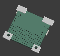 Let’s just draw these in the first sketch – four blocks, with two of them holding mounting holes. For the blocks with holes, if your printer nozzle size is the usual 0.4 mm, my understanding is that you’ll want to have your thinnest structure be around 1.2 mm. So, setting the hole diameter (refer to the toolbar, or just click D to summon the diameter tool), and for distances between points, you can use the general distance tool (K,D, click K then click D). Then, exit the sketch.
To The Floor And Beyond
Perfect – remember, the first sketch is already extruded, so when we re-drew the sketch, it all re-extruded anew, and we have the block we actually want. Now, remember the part about how to start a sketch? Single click on a surface so it gets highlighted green, press “New sketch”, and click “ok” on the box that asks if you want to do it the “Plane X-Y” way. That’s it, that’s your new sketch.
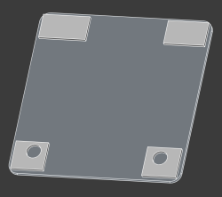
Now, we need to draw the box’s “floor”. That’s simple too – just draw a big rectangle. You’ll want to get some dimensions going, of course. Here, you can use the general distance constraint (K,D, click K then click D), or constrain even quicker by clicking I (vertical dimension) and L (horizontal dimension). Now, for the fun part – filleting! Simply put, you want to round the box corners for sure, nobody wants a box with jagged sharp holes.
You might have seen the Fillet tool in the Part workbench. Well, most of the time, it isn’t even needed, and frankly, you don’t want to use it if a simpler option exists. Instead, here, just use a sketch fillet – above in the toolbar; sadly, no keybind here. Then, click on corners you want rounded, exit the tool, then set their radius with diameter tool (D), as default radii are way too large at our scale. The sketch fillet tool basically just creates arcs for you – you can always draw the arcs yourself too, but it’s way easier this way.
 You got yourself a rounded corners rectangle, which, naturally, means that you’ll be getting a cease and desist from multiple smartphone makers shortly. You might notice that the rectangle is offset, and really, you’d want it aligned. Fortunately, we placed our STEP-imported board approximately in the center of the screen, which makes the job very easy, you just need the rectangle centered. Draw two construction lines (G,N) from opposite corners of the sketch. Then, click on one of the lines, click on the sketch center point, and make them coincident (C). Do the same with the second line, and you’ll have the sketch center point on the intersection of the two lines, which will make the whole sketch centered.
Extrude that to 1 mm, or your favourite multiple of your layer height when slicing the print, and that’s the base of your case, the part that will be catching the floor. Honestly, for pin insulation purposes, this already is more than enough. Feel free to give it ears so that it can be mounted with screws onto a surface, or maybe cat ears so it can bring you joy. If you’re not intimidated by both the technical complexity and the depravity of it, you can even give it human ears, making your PCB case a fitting hacking desk accessory for a world where surveillance has become ubiquitous. In case you unironically want to do this, importing a 3D model should be sufficient.
Build Up This Wall!
Make a sketch at the top of the floor, on the side that you’ll want the walls to “grow out of”. For the walls, you’ll naturally want them to align with the sides of the floor. This is where you can easily use external geometry references. Use the “Create external geometry” tool (G, X) and click on all the 8 edges (4 lines and 4 arcs) of the floor. Now, simply draw over these external geometry with line and arc tool, making sure that your line start and end points snap to points of external geometry.
 Make an inset copy of the edges, extrude the sketch, and you’re good to go. Now, did you happen to end up with walls that are eerily hollowed out? There’s two reasons for that. The first reason is, your extruded block got set to “solid: false” in its settings. Toggle that back, of course, but mistaken be not, it’s no accident, it happens when you extrude a sketch and some of the sketch lines endpoints are not as coincident as you intended them to be. Simply put, there are gaps in the sketch — the same kind of gaps you get if you don’t properly snap the Edge.Cuts lines in KiCad.
To fix that, you can go box-select the intersection points with your mouse, and click C for a coincident constraint. Sometimes the sketch will fail. To the best of my knowledge, it’s a weird bug in KiCad, and it tends to happen specifically where external geometry to other solids is involved. Oh well, you can generally make it work by approaching it a few times. If everything fails, you can set distance (K,D) to 0, and if that fails, set vertical distance (I) and then horizontal distance (L) to zero, that should be more than good enough.
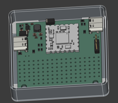
And with that, the wall is done. But it still needs USB-C socket holes. Cutting holes in FreeCAD is quite easy, even for a newcomer. You make a solid block that goes “into” your model exactly in the way you want the cut to be made. Then, in Part workbench, click the base model that you want cut in the tree view, click the solid block model, and use the “Cut” tool. Important note – when using the “Cut” tool, you have to first click on the base object, and then the tool. If you do it in reverse, you cut out the pieces you actually want to save, which is vaguely equivalent to peeling potatoes and then trashing the potatoes instead of the peels.
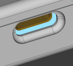 Want a souvenir? In Part toolbox, click Chamfer, click on the USB-C opening edges, set chamfer distance to something lower than your wall thickness, say, 0.6 mm (important!), and press Ok. Now your case has USB-C openings with chamfers that as if direct the plug into the receptacle – it’s the nicer and more professional way to do USB-C openings, after all.
Stepping Up
Once you get past “Hello World”, and want to speed your FreeCAD work tremendously, you will want to learn the keybinds. Once again, the key to designing quickly and comfortably is having one hand on keyboard and another hand on mouse, doesn’t matter if you’re doing PCBs or 3D models. And the keybinds are very mnemonic: “d” is dimension, “c” is coincident.
Another tip is saving your project often. Yet another one is keeping your FreeCAD models in Git, and even publishing them on GitHub/GitLab – sure, they’re binary files, but revision control is worth it even if you can’t easily diff the files. We could always use more public 3D models with FreeCAD sources. People not publishing their source files has long been a silent killer of ideas in the world of 3D printing, as opposed to whatever theories about patents might be floating around the web. If you want something designed to your needs, the quickest thing tends to be taking someone else’s project and modifying it, which is why we need for sharing culture so that we can all finally stop reinventing all the wheels our projects may require.
This is more than enough to ready you up for basic designs, if you ask me. Go get that case done, throw it on GitHub, and revel in knowing your board is that much less likely to accidentally short-circuit. It’s a very nice addition for a board intended to handle 100 W worth of power, and now it can also serve as a design example for your own needs. Next time, let’s talk about a number of good practices worth attending to if you want your FreeCAD models to last.


if i understand correctly, the topological naming problem is why i prefer csg
Unfortunately, CSG doesn’t inherently fix the topological naming problem. The naming problem still applies to the intermediate objects you build with solid geometry. For example: create a cylinder named “my foundation”, and add a cone on top called “pointy hat”, anchored to top of “cylinder”. Now decide you want to subtract another cylinder from the first, and call the result “foundation donut”. What is “pointy hat” anchored to: “my foundation” or “foundation donut”? The construction has forked, and now pointy hat is sitting in mid air-over donut; how can it be anchored solid in the final construct? And this is with just 3 simple components; next create an object with 100 components. It’s not a simple problem to have “one right answer” on how to solve all of this and catch inconsistencies.
i’m hoping if my ignorance is on display here, it’ll be a learning experience for me :)
but i have the idea that traditional cad gives you the opportunity to like…draw a complex shape in 2D, extrude it into a 3D shape, and then apply a uniform operation like bevel / chamfer to all of the places where the flat “top” intersects with the complicated “sides”? and on top of that, you can like make a second object, and anchor it to that “top”.
if i’m understanding that correctly, i can see the appeal. like, if it’s really a complicated shape that i extruded, then it will be a pain in the butt for me to chamfer each of its edges using a CSG tool like openscad.
but i intuitively don’t like it. and for the kind of work that i do, i never saw the point of it. and anyways, i prefer to edit text source, so openscad is the first CAD i ever learned and why shouldn’t it be the last :)
but the thing is, i don’t anchor.
i mean i still have a topological naming problem, but i solve it ad hoc for each project when i decide what kind of module() heirarchy i’ll use, and what i’ll name my parameters. and the names are the names i assigned and they don’t change unless i change them. i never assume that an extrusion has a top and a bottom, and that assumption won’t be invalidated if i replace the underlying object with a different primitive.
of course that puts an onus on me to factor and to use good names. i have used a bunch of styles for that over the years and i’ll freely admit that probably my biggest strength is that my projects aren’t so complicated that it really matters :)
It sounds like what you are describing is exactly what you have to do in any CAD package to never hit the computer guesses for you or undefined behaviour when you change a foundational feature others are built off.
One of the things I really loved about FreeCAD when I first started using it was the parametric modelling with that handy spreadsheet as it means you are never needing to anchor a part off another part, or locate an operation based on a part feature you might change later – everything’s position can be defined formulaically from the the same length/width/radius (etc) variables that define the part it is supposed to be attached to in the sheet you’d want to adjust that have sent the computer into a fit of ‘help I don’t know what to do here!’
You are also correct the biggest advantage IMO of the regular CAD is the ability to do things like chamfer complex shapes simply by selecting the vertex or edge you need the operation to happen on and telling it 4mm feature size. So for relatively quick and dirty models you know you’ll not need to really tweak the design heavily it is very very quick – drop the cube in, cut the sketch out, fillet the edges you need, nothing is properly constrained but its all in the right place for now, but all taking likely less time than just forming that complex sketch shape in the most primitive awful to work with later way in something like OpenSCAD.
One of the things they teach you in design for manufacturing is, you never stack references (or tolerances). Whatever feature you define, you reference it to a common point, your “home” point, so the machinist does not have to measure the actual width of the face they just cut to then define the other cut – slowing everything down and making things highly variable.
The same applies to parametric modeling. The topological naming problem “goes away” if you don’t stack your references. If you always refer to the same origin, placing your construction lines or points relative to the place where it all started, that does not change whatever you do, then each addition can exist in parallel. That is somewhat what CSG is about, when done right, and where CSG breaks down is when you don’t follow good practices.
Feature editing CAD programs on the other hand do stack up references, because that’s the entire point. It “emulates” they way a part is actually made in successive operations, so the problem becomes about the program detecting when it is about to break references and basically warning you and refusing to change references which are needed further down the tree.
yes
On the KiCad forum, there are also a few FreeCAD show cases, for example the thread below (From 2021).
In one of he posts in that thread, a 3D model of a Hammond case is imported into FreeCAD, then a “loop” is extracted, an offset applied, and the PCB outline is created from that.
https://forum.kicad.info/t/pcb-shape-from-enclosure-step-file/30935/
I’ve been doing the FreeCAD to/from KiCad thing a bit lately, and it’s pretty cool. I basically did what you outlined in that thread with the “KiCadStepup” workbench/extension: pulling a STEP from KiCad, modifying it in FreeCAD, and exporting a board shape back.
Only trick, AFAIK, is that you because you pull the model in from KiCad as a STEP file, you have to reference the geometry with the whole subshape binder mess to make your own sketch based on it. Is this a bug or a feature? It’s really nice to have the full parametric model in FreeCAD over and above the STEP file and/or tech drawings.
Otherwise, it’s pretty damn painless, and a very nice workflow if you’re doing a PCB with complicated mechanicals and maybe a case, and so on.
I think you can put the PCB outline directly from a sketch in FreeCAD to the Edge.Cuts layer in KiCad. But it has been years ago that I experimented a bit with KiCad StepUP, and even then it was a few simple tests. KiCad StepUP has a lot of buttons.
For me personally, I don’t make many PCB’s and the ones I do are mostly rectangular. Therefore I prefer simple tools. And though I use FreeCAD quite a lot, KiCad StepUP would be another learning curve. Each new workbench in FreeCAD is a struggle for me, and If I don’t use it often enough, then I already forgot it again by the next time I need it.
“Draw two construction lines (G,N) from opposite corners of the sketch. Then, click on one of the lines, click on the sketch center point, and make them coincident (C). Do the same with the second line, ”
You could use the symmetry constraint on the corners and centre point to do this. Or, better, use the’centered rectangle’ button to start with.
“Now, simply draw over these external geometry with line and arc tool”
Or extrude the sketch the full height and use a thickness. Quicker and more robust.
Or check ‘frame’ when you draw the first rectangle.
Loads of ways to do the same thing, some quicker than others. Mang0 Jelly on youtube changed my life. I’m discovering tons of time savers by watching those vids.
“Mang0 Jelly on youtube changed my life.” Agreed! And there are a great crop of other YouTube channels doing FreeCAD tutorials these days too. It’s picking up traction.
Biggest problem with my FreeCAD early user experience was all the old version tutorials that are now completely wrong.
Of course these are all un-versioned, undated and abandoned.
Give away is referencing workbenches that no longer exist.
People should bury their poo.
Old Testament PMS God says!
I’ve been trying to get into freecad and that’s the issue i’m running into. I’m following a tutorial and i have to select an option that’s just not there. It’s so frustrating. And the tutorial makers assume you know things and go through the difficult parts at insane speed, then slow down for the easy stuff. This is why I’m still using tinkercad after 8 years of 3d printing.
My problem is I’ve watched these videos and liked them. “Oh that makes it easy, oh that’s cool” … Then I forget as I don’t use FreeCad ‘every day’. Maybe once a month? :rolleyes: One of those ‘use it’ or ‘loose it’ experiences.
Hi do you need help on rapid prototyping?
Thank you! Is there a chance we will ever see a video tutorial out of this?
The ‘Claude’ AI engine can now control FreeCAD directly. I used neka-nat’s excellent MCP Server. For my simple purposes (generating STEP and IGES files of some simple metalwork), it was perfect. I imported KiCAD Gerbers directly into the conversation and Claude did the rest.
The topological naming problem is no more. FreeCad 1.0 + is very nice to use.