A lot of claims have been made about the purported benefits of adding chopped carbon fiber to FDM filaments, but how many of these claims are actually true? In the case of PLA at least, the [I built a thing] channel on YouTube makes a convincing case that for PLA filament, the presence of chopped CF can be considered a contaminant that weakens the part.
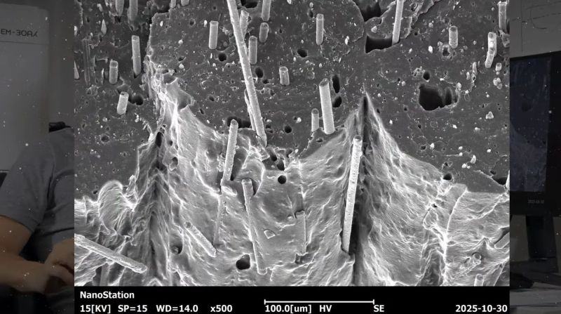
Using the facilities of the University of Basel for its advanced imaging gear, the PLA-CF parts were subjected to both scanning electron microscope (SEM) and Micro CT imaging. The SEM images were performed on the fracture surfaces of parts that were snapped to see what this revealed about the internal structure. From this, it becomes apparent that the chopped fibers distribute themselves both inside and between the layers, with no significant adherence between the PLA polymer and the CF. There is also evidence for voids created by the presence of the CF.
To confirm this, an intact PLA-CF print was scanned using a Micro CT scanner over 13 hours. This confirmed the SEM findings, in that the voids were clearly visible, as was the lack of integration of the CF into the polymer. This latter point shouldn’t be surprising, as the thermal coefficient of PLA is much higher than that of the roughly zero-to-negative of CF. This translates into a cooling PLA part shrinking around the CF, thus creating the voids.
What this means is that for PLA-CF, the presence of CF is by all measures an undesirable contaminant that effectively compromises it as much as having significant moisture in the filament before printing. Although for other thermoplastics used with FDM printing, chopped CF may make more sense, with PLA-CF, you’re effectively throwing away money for worse results.
As also noted in the video, in medical settings, these CF-reinforced FDM filaments aren’t permitted due to the chopped CF fragments. This topic has featured more widely in both the scientific literature and YouTube videos in recent years, with some significant indications that fragments of these chopped fibers can have asbestos-like implications when inhaled.
Meanwhile, are you’re looking for the thrill of a weird filament? Maybe try one of these.


Would like to see this done for ABS/ASA – GF/CF and Nylon (PA)- CF/GF
Just found this after a quick search:
Wang, Z.; Fang, Z.; Xie, Z.; Smith, D.E. A Review on Microstructural Formations of Discontinuous Fiber-Reinforced Polymer Composites Prepared via Material Extrusion Additive Manufacturing: Fiber Orientation, Fiber Attrition, and Micro-Voids Distribution. Polymers 2022, 14, 4941. https://doi.org/10.3390/polym14224941 (open access)
under 4. Micro-Voids
under SEM , and CT sca they look similar. what can aso be told about that filament is that the CF loading is ludicrous being benevolent…..
I’m not all too surprised if the conclusions are true, but it needs more eyes and more rigorous testing to be convincing. It is possible I’ve missed it, but the video doesn’t give many details on the specific filament, his printer and settings. Ideally the tests are repeated for multiple brands of filament, printer profiles, etc.
this is consistent with other test results I’ve seen
i don’t know of any rigorous comparison of brands and settings but the consensus seems to be that cf makes parts stiffer and less prone to warping, but ultimately less strong
True. sometimes comparisons are difficult as loadings aren’t reported. this one seems to be quite lightly. sometimes also happens that low loadings do more harm than no filled polymers
100um scale is on image.
The testers ‘mistake’ * was using a 0.2 mm nozzle w fiber reinforced filament.
Using wrong printer settings, notably too thick a layer for 0.2 mm nozzle.
No squish, like a bad date.
a ‘mistake’ that got him views.
I looked through the transcript of the video for the nozzle size used but didn’t see anything. Where in the video does it mention the nozzle diameter? Or was that in a previous video by this guy?
The image above shows a 100um scale.
The plastic beads are each two of the scales wide.
200um = 0.2mm
The plastic beads are also still round.
Which means he had the layer thickness = the nozzle size.
Flow Ratio at 1 or maybe even lower.
Bluntly, he rigged the test to get bad results.
Well spotted – all the advice I’ve seen is that 0.4mm is about the minimum and larger is recommended for filaments with stuff added, and I can easily imagine squeezing this mixture through too thin a nozzle would affect how it actually ends up being laid down.
Also, perhaps the article should reference a few of the many tests done by reputable channels on the strength of these filaments vs regular ones as those guys have contributed a lot of relevant data to the discussion.
Hey I saw it on You tube it has to be real
The issue I have with these findings is that there’s no comparison with a control group, at least as far as the SEM imagery is concerned. Also, even if it visibly looks contaminated and seems obvious that the supposed contamination on display would weaken parts, what it should come down to is rigorous testing of the parts under different load and strain scenarios, like what Stefan of CNC Kitchen has been doing for years.
In my own experience, PA-CF has been incredibly sturdy compared to PETG and PLA, but I haven’t ever compared it to plain PA. I’ve been hesitant to keep using it mostly because of the potential health effects of CF fibers that I’m exposed to during post-processing, and I haven’t had a need to make a structural part in a while anyway.
Oh also does the CF have to be integrated into the base filament for it to be effective? We have centuries of experience showing that inclusions make concrete much stronger, even though it’s not chemically bonded in (at least in the case of rebar).
Look at injection molding for guidance.
Glass reinforced nylon is common, it’s a goto material.
CF reinforced nylon is also becoming common, but has known hazards beyond glass.
I haven’t read the science, but I bet there are many scientist years in the study of how the nylons wet fibers and how the fibers interact with the nylon structure as it crystalizes (or doesn’t).
Rebar is an apt comparison, amorphous nylon will physically wrap itself around stuff, mostly other amorphous nylon but also jaggy reinforcement like glass fiber.
I use GF reinforced nylon for structure, any fiber helps w part warping.
Skeptical CF is worth the hazard and extra cost.
Pretty sure all the filament is nylon 6.
Anybody know if there are any 6-6 filaments?
Anyhow, Z-layer adhesion says ‘Hi…What’s this itchy crud’.
Glass-reinforced nylon, PC, ABS, PBT, PPO/PPE, PPS are all widely used in injection molding and have been for decades. Anecdotally, the only time I have ever seen chopped carbon fiber-reinforced injection molded parts in the wild is in 1990s vintage laptops (including the metalized internal frames in most PowerBooks – according to the book “Designed by Apple in California” these are CFRP) , and they were always extremely brittle. Maybe there is a good reason why CF is not widely used.
Model airplane propellers are sometimes CF reinforced nylon.
It’s a high cost option for props shot in the same molds as the standard glass filled ones.
Looking at you APC…
Also, IIRC there is a marketing term for injection molded ‘CF parts’ that pretends they are high end…
‘Cast carbon fiber’ or some such bs.
Ricers are weird.
Italian trash aficionados even weirder.
Common mold making software like Solidworks can put a fake ‘laid up carbon fiber cloth’ surface finish on those, to complete the illusion.
Assuming you’re aware of the wide availability of PA12 filaments. As to copolymers containing PA6, PA6/66 is readily available as is PA6/12 – check out Inslogic and 3DXTech in particular, just don’t faint from the sticker shock. I can’t recall where, but I did PA66 available at one point. Prusa makes (made?) a PA11 which is kinda meh; selling point is renewable feedstocks to manufacture it. In even stranger territory, I saw a PA4085 (IIRC) on Amazon a few days ago. It was firmly in “must sell kidney to afford” territory, so I didn’t really look too hard into it.
Anyhow, yeah, there are quite a few nylons readily available in what I would still call the hobbyist affordable range. Whether the extra cost is justified for the application is an entirely different matter.
Oooh. Screw CF. Let’s use rebar in PLA! Except it’s too big and won’t bend through most nozzles. Best grind it all up into micro shards and mix it with the PLA base. Just don’t touch those finished prints with bare hands.
To be clear though, the OP is talking about carbon fiber added to PLA, not PA (nylon).
Personally, I’ve always been skeptical about the entire concept of strong 3D filaments (in hobbyist contexts), because the strength of parts is so obviously not determined by the bulk properties of the material in the first place. It sounds like trying to make a brick wall stronger by using steel bricks.
I realize highly-tuned processes might be able to do better than that (which is why you can spend 5+ figures on an FDM printer). But for regular folks who have a hard enough time getting plain PLA to stick to itself consistently, you’re not going to get magic results by just buying the right filament.
From my own experience as a student and hobbyist the material choice does make a relatively significant difference. Sure geometry and print settings also make a huge difference but the same part printed with the same basic settings printed in different materials, like PLA and PC can have pretty different mechanical properties even down to things like surface hardness and especially stiffness and friction.
As an example I was printing small parts with snap hooks with a 0.2 mm nozzle, I tried a few different materials with the exact same print, PETG, PA 6 and PC, there were very different properties between them.
You are right though, for most people who just need a strong part and not anything too out there then it may be easier and better to just bulk the part up rather than going for more suitable materials.
I believe plenty of folks have run & tested CF and GF filaments and report it is indeed usefully stronger, channels like CNC Kitchen and My Tech Fun have done some fairly decent testing on this stuff that shows real results without any fancy hardware beyond perhaps a harder nozzle of a slightly larger diameter.
If you’re having trouble getting basic PLA to hold together I would suggest a more modern printer might be in order, things have come a long way in the last 5-10 years.
“This translates into a cooling PLA part shrinking around the CF, thus creating the voids.”
Shouldn’t it shrink around the CF, pushing harder against it? In thermal expansion, holes shrink when the material shrinks.
Molten plastic is a compressible liquid.
Some have useful non-Euclidian liquid properties.
Behaves in unintuitive ways.
e.g. It thins when pushed through a small orifice (insert ‘your mom’ joke here).
Hydraulic forces on a fiber through a solidifying skin on a molten bit of plastic could ‘squeeze out’ the fiber in interesting ways.
Devil in details of plastic.
Both the CF and the PLA is affected by the heat at the same time, so it’s dependent on what the CF does when cooling as well as the PLA
According to google there’s some suggestion that the CF might shrink slightly instead of expanding when subjected to heat, if that happens then the you might end up with gaps or voids between the CF and the PLA which is what is suggested above
holes get bigger when things cool. train wheels axel holes are fit to the same size as the axel (or just smaller), then cooled down with liquid nitrogen and slid over the axel. super cooled the holes get bigger, not smaller. as they warm up, they pressure fit to the axel and will basically not move.
Huh, I’ve never heard about that before! I’ve just seen the outer part being heated and axle being cooled.
Do you have a link with more information about these “super cooled” holes that increase in diameter?
I think you’re misunderstanding how that works. In a disk, a central hole will increase in size when the part is heated, not decrease. This is a very common school experiment/demonstration, and was explained even more in my first year of mech eng. The liquid nitrogen cooling method is done on the axle, not the wheel, to shrink the axle enough to slip the wheel on.
In the context of the article, I believe the article and video implies that there’s other weird properties of plastic at play that counteract this effect, causing the plastic to pull away from the fibers.
Old English sports cars manufacturers loved to marry parts together using this method.
Of course it was just the parts that needed to be disconnected most commonly.
IIRC for the disk/wheel, it depends on the ratio of OD to ID and bunch of other factors.
Train wheels are GD metallurgical turduckhen.
Wow, I learned something today. Thanks.
At higher filler fractions, matrix shrinkage can indeed create voids, but for that to happen the fibers need to be packed so densely that they nearly touch, or touch in multiple spots.
Here it looks like the blending of the fibers into the polymer matrix was the problem. Perhaps the extruder that made the filament wasn’t powerful enough, or the filler fraction was too high, which usually leads to voids when fibers bunch up into bundles without the matrix penetrating into the space between them.
At low filler fractions, the idea of longitudinal void formation through cool-down is challenged. Since the fibers do not chemically bond with the matrix (no adhesion promoters, no functional groups and very little mechanical interlocking), I’d rather expect radial cracks to show up where the fibers force the matrix to be under tension.
So yeah, voids are more likely due to improper admixture of the filler.
Bet the filament doesn’t look like that.
Bet the granules the filament was made from don’t look like that.
The extruder w the problem is on the printer.
I’d bump up the flow ratio and extruder temperature.
Bump down the layer height.
Not looking for ’round’, rather, squished, melted together w neighbors.
From the image, was using a 0.2mm nozzle.
This isn’t recommended for fiber.
Might be the heart of the matter.
Fibers align w the flow of plastic.
These rounds did a gentile bend to horizontal.
Would be much better if they had done a turbulent sploosh from a larger orifice (like cocaine Pam).
i have a better idea! chopped asbestos!
Another insightful and useful comment from Gus. What would we do without you.
Who even used PLA CF? PA6 CF is what people use.
I’ve used Polylite PLA-CF and was able make a large load-bearing part 48% lighter (using 40% less infill) and it outlasted the standard PLA version. Just my experience. You can also achieve a fairly convincing carbon weave look using those decorative patterned optional build plates. Indeed, after a few jobs I did noticed a concerning amount of black fiber strands around the workspace. They easily become airborne and would do ‘a real number on the lungs’, no doubt. Exercise caution…
Come on HaD writers, the video is at the very least structured as clickbait and there’s a whole slew of well known 3D printing channels who have run very sensible tests on CF filaments and shown real data on the strength of printed parts printed on regular printers.
I know sensationalism sells and that’s why the video is made the way it is – but credulously and uncritically reporting on a sensationalist youtube video is not helping either.