It used to be a rite of passage to be able to do the math necessary to design various bipolar transistor amplifier configurations. This doesn’t come up as often as it used to, but it is still a good skill to have, and [Void Electronics] walks us through a common emitter amplifier in a recent video you can see below.
The input design parameters are the gain and the collector voltage. You also have to pick a reasonable collector current within the range for your proposed device that provides enough power to the load. You also pick a quiescent voltage which, if you don’t have a good reason for picking a different value, will usually be half the supply voltage.
The calculations are approximate since the base-emitter voltage drop will vary by temperature, among other things. But, of course, real resistors won’t have the exact values you want, or even the exact value marked on them, so you need a little flexibility, anyway.
There are other ways to approach the design. But most design guides will make the same assumptions: Ic=Ie, base current is negligible, and similar simplifying assumptions.
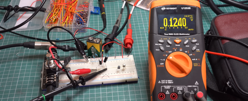
At the end, the circuit winds up on a breadboard so you can see how close the predicted performance is to the design.
We’ve covered biasing bipolar devices a number of times. We’ve even modeled circuit variations in a spreadsheet.


It certainly was a right of passage back when I first learned how to design common emitter amplifiers at the age of sixteen. Two and a half years later I was in college and that spring semester I aced my solid circuits class. Back then you could design amplifier in all three configurations with ease.
Knowing how to design basic circuits like this; is not only empowering but can get you out of a jam when you need a simple minded circuit.
A Class A presentation.
Interesting he left out the bypass capacitor on the emitter resistor — an important part of a ‘real’ amplifier.
Now, what about that nifty Class E amp that the cool kids are using now with the HELAPS RF amplifiers?
I slogged through two years of a 3-yr Electrical Technology program at college, then I found out that the Physics kids got a one-semester electronics course that took them from basic Ohms Law stuff to quick designing using transistors and opamps. They were doing design stuff that we hadn’t even got to yet! Their text was… “The Art of Electronics” by Horowitz & Hill. I bought that book, pitched all the rest, and didn’t look back. That book nicely covers the basics, but also leaves the reader with a set of recipes for quickly designing the most common electronic functions like transistor amps.
I earned an AS degree we got into transistors at the beginning of the second semester. For anybody who got a passing grade in high school math had little or no problems with the study material in the program.
99boncasino looks pretty slick! Lots of different games to choose from so easy to find something that is to your taste. I’d suggest looking at 99boncasino
The freshcasinoapp is surprisingly well optimized. Runs smooth on my phone, even on some of the more intense games. Definitely an upgrade from some other apps I’ve used. Download freshcasinoapp if you’re into mobile gaming.
Hiperbbet is a new one for me, but I’m digging the overall vibe. Good selection of sports and the live betting options are pretty comprehensive. Give hiperbbet a look if you’re after something different.