If you’ve got a decent CRT monitor, you can usually adjust the settings to make sure the image scans nicely across the whole display. But what if you could rotate the whole image itself? [Jeri Ellsworth] has shown us how to achieve this with an amusing mechanical hack.
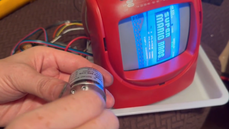
The trick behind this is simple. On a standard CRT, the deflection yoke uses magnetic coils to steer the electron beam in the X and Y axes, spraying electrons at the phosphors as needed. To rotate the display as a whole, you could do some complicated maths and change how you drive the coils and steer the electron beams… or you could just rotate the entire yoke instead. [Jeri] achieves this by putting the whole deflection yoke on a custom slip ring assembly. This allows it to receive power and signal as it rotates around the neck of the tube, driven by a stepper motor.
Amusingly, [Jeri] even found a super nifty way to drive the stepper. There are no microcontrollers or fancy driver logic here—instead, the quadrature output from a rotary encoder outputs a perfectly legible pulse train which can drive the stepper as needed. [Jeri] notes this provides a nicely instantaneous response. There’s still work to be done, too. The project is due to get a 3D-printed housing, a homing system, and some improvements to the DIY slip ring setup.
If [Jeri’s] name sounds familiar, that’s because she’s built many a grand project over the years. You might have seen her work on the C64 DTV or the breadbin keytar.
I have big plans for spinny CRT
— Jeri Ellsworth (@jeriellsworth.bsky.social) 2026-01-05T10:42:52.953Z
[Thanks to Neonsystem95 for the tip!]


I feel like this can be done without moving parts…
It would involve some very difficult math though because you’d need to recalculate electron beam as it flies through magnetic field. I’m not saying it’s impossible but you’d need MATLAB license.
you have magnetic field given by X and Y coils, each having voltage proportional to X and Y coordinates of the beam. Rotating that space sounds like some basic trigonometry and/or multiplication by 2×2 matrix… you just need ADC to read 2 coil current/voltages, fast mcu to digitaly rotate the vector and DAC to drive the actual coils. you can probably put such device directly between the electronics and coils. if you are lucky enough, you can tap such device into signal just before power frontend that drives the coils to avoid having to implement the amplifier yourself…
define “fast”
“fast mcu to digitaly rotate the vector and DAC to drive the actual coils. you can probably put such device directly between the electronics and coils”
Or just a resistor capacitor circuit.
Since it’s magnetic deflection, the beam position is proportional to the current in the yoke coils.
Geez, all you need is a bunch of oscillators , the way they did it in the 60s
Scanamate
https://vimeo.com/172607783
and the Paik-Abe Video Synthesizer, and Bill Hearn’s Vidium
Google will find the other two
It’s too bad that there wasn’t really any high definition analogue video, there is so much in analogue that a few resistors, capacitors and op amps can do that you don’t need all that math and GPUs for. I mean there’s math but the capacitors are doing it. Or a pendulum if you have enough time. There is a photographic machine that does that but it takes an hour or so per frame with a photocell a lamp and a pendulum.
Btw, ever wonder why they call them plugins? Watch that video.
amusingly there is an analog high definition “standard” which is used for CCTV cameras
The two coils are not identical. They have different amount of windings and inductance. Using the vertical coil to do the horizontal scanning isn’t going to work. Too high inductance (too slow).
2d rotation matrices are literally covered in high-school pre-calculus maybe even Algebra 2. Are you absolutely sure you can’t just use one of those?
Depends on what country you are member of at the time when going to a high-school and what teacher sees appropriate to teach. For example our class ended with only
y = ax² + bx + cequation and its transformations (delta etc.) before final exams. When I emigrated to Romania and started studying electronics at the university I realized I don’t know shit about matrices or integrals.I’m sure it could but I like the old school mechanicalness of this approch.
cool you just repeated sentence 6 of this article, which says:
“To rotate the display as a whole, you could do some complicated maths and change how you drive the coils and steer the electron beams… or you could just rotate the entire yoke instead.”
The whole idea behind this project is to keeping it simple by doing it WITH moving parts. Although simple is a relative term biased by what you are familiar with.
You could also rotate the viewer. Just make sure they’re strapped in securely.
You are designing a vector monitor. Since you can’t rely on the horizontal coil being scanned fast enough to generate the high voltage flyback pulses, instead of using a flyback transformer, you’ll have to get the high voltage for the CRT anode elsewhere (like in vector monitors – they do have flybacks, but these are disconnected from the yoke).
Just wire an inductor in instead of the deflection coil. Easy enough (i’ve done it a couple of times)
You have wound an inductor capable of producing high enough voltage for a color CRT?
There are easier ways.
Rotating the image with no moving parts is easy with an electrostatic-deflection CRT, like from an oscilloscope.
Even the math is trivial.
Doing it with a magnetic yoke is a bit more difficult. As SDS points out, you’ll need to ensure you have a HV supply, often (not always!) provided by the horizontal scan circuit. But you’ll also need to provide drive circuitry for the yoke coils that don’t rely on driving a resonant circuit — the horizontal and vertical frequencies differ by a factor of 525.
But I’d really like to hear what Jeri is planning with this — it looks like something fun.
For what it’s worth, there were WW2 radar displays using magnetic-deflection CRTs, which featured rotating yokes.
Not sure what the end-game is for this project, but spinning a yoke to rotate a screen image on a CRT is actually well-travelled ground.
Then nobody would care.
Thats is like watching the trapeze act at the circus then being like “They could have just walked to the other side of the tent.” Factually accurate, but boring.
Uh yeah you could transform the video digitally on a pi and use the TV out pins ;)
It’s so stupid I love it! :-D
This is so incredibly irresponsible! If you do this to a color CRT you damage it permanently. And nowhere here does it say that. So you’re encouraging thousands of people to go and destroy the precious CRTs that probably took them a lot of time and effort to procure.
I think you need to expand on your reasons why it will damage a colour CRT. Especially given that the CRT in the video is colour and seems to be undamaged.
I guess they’re thinking about the beams hitting the mask. I’ve no idea how destructive this is (though it being a ‘mask’ implies not very). The TV in the video very much looks mono.
The beams hit the mask whether you rotate or not – surely? That’s why the mask is there.
I’m missing something that both of you can see though – I see red, blue, and white on the screen, which makes it colour to my eyes.
Buried in the comments, Jeri confims it is a 5″ mono CRT. She also says she’d played with a colour one and it seemed ‘mostly ok’. I suspect a Trinitron would not play as nice!
nehh… if you really think that thousands of people are going to destroy their CRT by replicating this project then I really wonder how many people do you think are reading this, have a CRT, dare to modify it, are actually willing to modify it and if so in what condition would that CRT be and what would happen with it otherwise. So I guess in the end that would be perhaps one or two… world wide.
Let’s face it, not every CRT is worth saving, projects like these actually could give them a new life, put them in the spotlights and cause other CRT’s to be noticed and saved. So in the end this project might even revive the interest in CRT’s preventing them from being thrown away.
Regarding the project, I like the out-of the box thinking here.
Damage it permanently? By knocking the purity magnets off (because they’re glued to the yoke and the CRT)?
No. You will twack convergence and purity and if you’ve got a self-converging in-line CRT, it’ll be only noticeable in the corners.
Some color CRTs are very sensitive. Getting the color purity and convergence right after returning the CRT to stock will be a PITA (especially since you have to re-position and then re-glue every purity magnet), but it can be done. But I’ve also seen CRTs that barely care and you’d be hard pressed to notice a difference.
Background: I’ve watched a TV repairman in his workshop, fixing arcade monitors. It’s easier and takes up less space to send him the broken monitor chassis. He takes a matching CRT from a shelf, mounts it in a jig, takes a matching yoke, just plops it on the CRT, hooks them up and tests it. When the chassis is fixed, there are some purity and convergence issues (and the picture is always crooked), but the CRT works fine and could be adjusted. He just doesn’t have to as the goal was to get the chassis working, not to have a perfect image on his test jig CRT. And if he wanted that, he could.
I’m also missing the point – let’s say you’ve made the modification and have a rotatable yoke and you’ve readjusted purity and convergence. Now you turn the yoke by 90° – at least the convergence (and if you have bad luck, the purity too) will be way out of whack. You might have to come up with 6(!) servos to rotate the purity/convergence rings based on settings that you have to program.
But damage permanently? Nope. You’ll just waste a bunch of time getting the image to look good again.
Nobody is going to do this. Don’t worry.
Please say syke
Many things in life are bad for your health, it’s not just CRT. According to American scientists living in a big city for 5 years is just as bad for your health as smoking a pack of cigarettes every day for 20 years.
Sorry, that was a reply to /u/briantw
There’s something wrong with comment system here.
Nothing wrong with the comment system. Just the commenters. I also couldn’t find any evidence to back up your claim. Yes, there is more pollution in cities, but that’s about it.
I’ve read that (also according to American scientists living in a big city for 5 years) being hit by a CRT dropped from the 3rd floor of an average building, can be just as lethal as being hit by a medium size sea container full of cigarettes (the ones with a filter) from the 2nd floor. Although results may vary depending on wind conditions and if the TV was plugged in before being dropped. The tests results did not mention if these were color TVs.
Photos, or it didn’t happen.
Hey! It seems we have a new epitome for esoterica (I’m trying to be polite here) on Hackaday!
But wait: Is that a slip ring she put on that rotating assembly? Hmmm…
Saw it was Jeri, jumped right to the video, skipped Lewin’s prose :-)
Jeri is on that very short list of people.
Interestingly, rotating the image like this is one step in an entirely-optical image reconstruction method for tomographic imaging, like x-ray CT. (Now to find that paper from 1975 or so…)
I could do with a source for low-resistance carbon brushes. I tried to make a slip-ring for a car horn switch on the steering wheel (didn’t fancy clock-spring wiring). The brushes I could find (on eBay) were for motors and turned out to have too high a resistance to work.
What kind of resistance are we talking, here? Maybe it was the material you were “brushing” or you didn’t have enough force pushing them together. There’s also a bit of a “break-in” period for these things while the two parts resurface each other to fit.
That’s odd: Car horns were driven through slip rings on steering wheels in the past. I can’t recall whether a relay was in the path though, or whether the slipring was called upon to carry the full horn current. In any case, an ‘ordinary’ carbon brush can easily carry ten amps.
In the few older cars I’ve worked on (vw beetle, triumph spitfire, olds cutlass) yes the slip rings took the full horn current which is why a lot of older cars had issues with the horn sometimes honking when you turned, when they were older. They definitely needed a relay with just the coil voltage through the horn button. (Some considerably older cars didn’t have slip rings: they had a long bundle of wires down the middle of the steering column that twisted over its length, but that stopped fast when people started insisting on collapsing steering columns.)
Probably had a relay. Even too long a wire will mute a horn pretty severely
Accidently reported your apologies as there is nothing wrong
That’s surprising to me. I’m pretty sure the original carbon brush in the horn assembly on my 1950 vehicle is nothing too special. With the amount of current that can run through the rotor on a motor, I wouldn’t expect a lot of resistance in the brushes themselves. (If so, would the motor run faster or more efficiently with worn brushes?)
How much current is going through your slip ring? Typically (in the olden days) that arrangement would just be driving a relay.
Reply to all:
The original steering column had a carbon brush system, but I’ve long lost that and spares are no-longer available, even through breakers.
Using the pencil system, I suspect the original brushes were the equivalent of 4B, nice and soft for good contact. Motor brushes are probably 4H for long-life. At high 110/220V resistance is less of a hindrance, but at 12V, passing through the brushes twice (to the wheel and back) was enough voltage drop that the horn wouldn’t work.
The display of a Raytheon marine radar of the 1950’s and 60’s has this. It is basically their late WWII unit for the the civilian market. It was standard for RADAR displays of all sorts. You can hear the motor while using one. Also the comforting high RPM spin-up of the Dynamotors that provide the higher voltages for the tube based electronics. Derived from the 12/24/48 volt environment of boat or aircraft.
I was going to make the same comment, were synchro motors were used to move the CRT coil to match the direction of the radar antenna.
Not how I would do it but quite fun!
A big ass permanent magnet or two rotating, or a couple of oscillators slightly out of sync with the video driving the deflection would be my solution.
The real world use case for this, historically, is radar display.