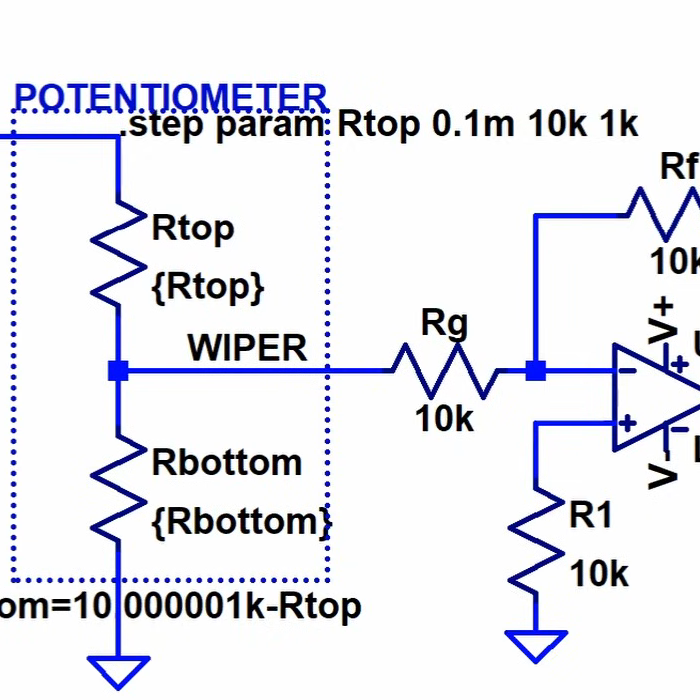
One of the good things about simulating circuits is that you can easily change component values trivially. In the real world, you might use a potentiometer or a pot to provide an adjustable value. However, as [Ralph] discovered, there’s no pot component in LTSpice. At first, he cobbled up a fake pot with two resistors, one representing the top terminal to the wiper, and the other one representing the wiper to the bottom terminal. Check it out in the video below.
At first, [Ralph] just set values for the two halves manually, making sure not to set either resistor to zero so as not to merge the nets. However, as you might guess, you can make the values parameters and then step them.
By using .step you can alter one of the resistor values. Then you can use a formula to compute the other resistor since the sum of the two resistors has to add up to the pot’s total value. That is, a 10K pot will have the two resistors always add up to 10K.
Of course, you could do this without the .step and simply change one value to automatically compute both resistors if you prefer.
We’ve done our own tutorials with .step and parameters if you want a little more context. You can even use this idea to make your own custom pot component.


The input voltage is being potentially divided. The gain of the amp remains at unity.
If you want your potentiometer to operate in constant current mode you should leave pin 3 ungrounded. This changes it from voltage divider to a rheostat.
Didn’t watch the video, but this is what I use:
.param rt=5k
.param ra=rt*rp+1m
.param rb=rt-ra+1m
.param rp=0.5
The resistors are {ra} and {rb}. rt is the overall value (5k here) and rp can be varied from 0.0 to 1.0 as the wiper position (50% here) using .step etc.
If anyone was wondering about the
+1m, it seems random, but serves a purpose:SPICE optimizes nets it knows are identical (supernodes). When the
.PARAMhits exactly 0 or 1 (without this tweak), the topology changes, and unexpected behavior, numerical instability, can happen.1mis a generic enough value, not likely to cause problems; in the rare case you use one of these for adjusting, like, a current-sense resistor (rt=10msay), you’ll find a problem, but you wouldn’t usually call a real component like that a “potentiometer”, and should reach for a different simulation solution. I suppose the technically-correct value should be around1/GMIN.The enterprise-grade solution should clamp the value of
rpitself (so that any value can’t cause weirdness: shorts or negative values). Just as well, we can avoid putting whole numbers into it. This modest tweak lets us use conveniently round numbers 0 ≤rp≤ 1 without having to code anything like that.Ahem… POTS = Plain Old Telephone Service ;-)
Interesting to me are the undanswered questions “Why?” does SPICE not have a built-in potentiometer, does SPICE have a built-in variable capacitor (tuner to us normal folk)?
R=(time)10K
R=(1-time)10K
I just use this, works pretty well
I had to figure this out by myself 2 days ago. I think I’ll check my PC for spyware…
I went with a DC source, set up a voltage sweep and set a net on the positive leg. then made the resistors dependent on that net
I find out that changing the resistor value works perfectly fine when built in the real world hardware. LTSpice precisely calculates it.