[Kevin] admits that FreeCAD may not be the ideal tool for editing STL files. But it is possible, and he shares some practical advice in the video below. If you want to get the most out of your 3D printer, it pays to be able to create new parts, and FreeCAD is a fine option for that. However, sometimes you download an STL from the Internet, and it just isn’t quite what you need.
Unlike native CAD formats, STLs are meshes of triangles, so you get very large numbers of items, which can be unwieldy. The first trick is to get the object exactly centered. That’s easy if you know how, but not easy if you are just eyeballing it.
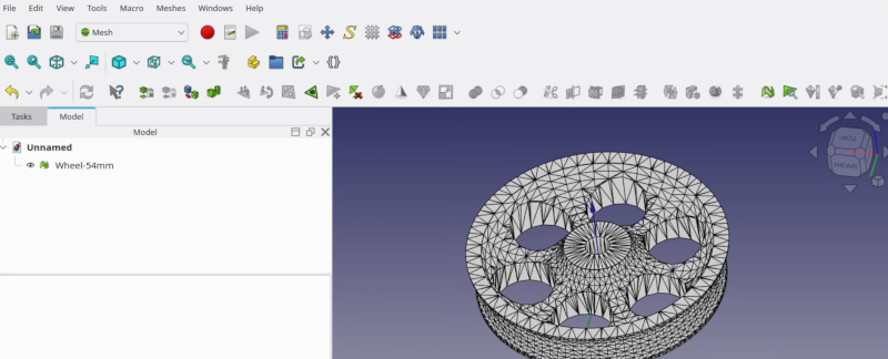
If you use the correct workbench, FreeCAD can analyze and fix mesh problems like non-manifold parts, flipped normals, and other issues. The example is a wheel with just over 6,000 faces, which is manageable. But complex objects may make FreeCAD slow. [Kevin] says you should be fine until the number of faces goes above 100,000. In that case, you can decimate the number of faces with, of course, a corresponding loss in resolution.
Once you are satisfied with the mesh, you can create a real FreeCAD shape from the mesh. The resulting object will be hollow, so the next step will be to convert the shape to a solid.
That still leaves many triangles when you really want flat surfaces to be, well, flat. The trick is to make a copy and use the “refine shape” option for the copy. Once you have a FreeCAD solid, you can do anything you can do in FreeCAD.
We’ve run our share of FreeCAD tips if you want more. There are other ways to tweak STLs, too.


When are we going to leave STL’s behind?
Seriously. People should just post FreeCAD files. It’s FREE software that can then be used to render STLs or anything else. I don’t even bother downloading STLs; I’d rather model what I need from scratch. STLs are like JPEGs of line art.
Or at bare minimum people should upload step files.
Probably never.
STL’s are easy to work with, easy to make, easy to edit. Almost everyone that works with 3D printers uses STL files. It’s the standard file format and it works, even if some dislike it. Not even all software supports STEP files. If you were to give me a STEP file I would have to figure out how to convert it to an STL file so I can import it. The last time I had to use a STEP file it took me a day to find a piece of software that could open the STEP file and actually display something useful. Some software could run, but after opening it up it made zero sense. Ended up with some online service instead.
It’s the same thing with word documents. I’d rather have people give me tex files or pdf files, depending on what I need to do with it, but here we are.
STL’s are easy to edit? WHAT? Give me STEP all day long. Any slicer can natively open STEP files. I’ll take a solid with easily editable faces over a crappy STL with a billion triangles I need to get rid of first any day.
Yes, STL’s are very easy to edit as all slicers and CAD software I know supports that. I’ve never even tried opening a STEP file in a slicer directly. I tried getting CAD software to open STEP files which was a pain. Can’t remember which one supported STEP, was well over a year ago. Might have been Onshape that I ended up using to look at the file. Most people that offer STEP files also offer STL files for people to print so I go directly to the STL files. Only when it’s complicated with dozens of STL files that need to be combined into one object it can be a good idea to look at what’s inside the STEP when combining all the different prints. Like a 3D version of a Ikea manual.
I have never ever dealt with triangles in STL files. I know STL’s in theory has triangles in them but I’ve never seen them myself or dealt with them. This article is the first time in my life I’ve actually seen the triangles and I’ve dealt with thousands of STL files. I always export to STL and then load the STL in my slicer. When I design something that I end up putting online for others, I upload the STL. I can try to find an STL to STEP converter but I figure others can do that too.
We clearly work in very different ways with different software and methods. And that’s why STL’s won’t go away.
With fast 3d printers, you can clearly hear the rattling on larger round paths when using STLs, because STLs and have a concept of curves but only straight edges. STEP allows to print much more smooth and with less stress on the printer.
So you basically admitting that you don’t even know what “editing” means.
Thanks for a useless rant.
You can use Cad Assistant (https://www.opencascade.com/products/cad-assistant/) to view and convert STEP files
Not really a good comparison, STL to Iges or step.
STL had only the bare minimum of mesh data. Imho it’s way easier to work with wavefront obj. STL can be a pain to render, cause of normal issues. It’s way easier to import and triangulate obj. As an extra it comes with proper normals, uv coordinates and material assignment.
An STL is like a binary file or a PDF and a STEP is like sourcecode. Not so many people like to share there source.
But I don’t understand why I should convert STL to a CAD model. If I have the skill to do this it is much easier made the complete model by your own.
No.
It is not generally true that ‘it is much easier…’
It depends on the STL.
Suppose you want to alter a STL in some way.
e.g. add cthulu wings and face to Mickey Mouse.
Find Cthulu, find mickey.
Chop chop, union, smooth edges (optional), export STL.
Halfassed, but done.
But ask yourself: Do you really want to taunt a demon prince?
Mr. Mouse is fearsome.
I’ve pulled plenty of STL files into FreeCAD to get their geometry directly and make my own bolt-on parts or mods or whatever. This would be a LOT easier if more creators shared STEP files, but some slicers still don’t take STEP directly so I can see why they don’t by default. There’s a bit of a problem with curves and holes in STL since they’re approximations, so finding a center is a few more steps than I’d have to do if I had a STEP file.
If we wanted to really go down the path of comparing model formats to code, I’d say the original design file (FCSTD, F3D, etc) is source, STEP is a library, and STL is relocatable object code. Not sure where that leaves g-code, maybe a VGA signal, haha?
A better comparison would be: STL is like a PNG file of a graphic, whereas the FreeCAD file is like an SVG. The PNG is baked-in and non-scalable and non-modifiable, whereas the SVG is a flexible source file that can be modified without losing quality.
No, JPEG it is. The STL compress the 3D coordinates to whatever is representable by the format. The typically processing pipeline is to go from a mathematically pure surface, sample it at some point frequency and/or tangency, mesh the result (resulting in a loss of precision). So it’s lossly all the way to the STL format, just like JPEG is for images.
And Step isn’t like SVG either, since it’s not parametric, it only describe the surfaces, not how you’ve made them, it’s not as lossy as STL.
Using freecad for an exchange format is better but not the panacea too. Freecad files are not standardized, their content evolves from version to version (in a non backward compatible way). The functions part depends on what workbench and tools you’ve in your installation. I know, because I’ve made a tool to convert STL to Freecad’s sketches.
The world desperately need a interchangeable parametric CAD format. STEP214 started to make some step in this direction (pun intended), but it’s very far from being enough or useful (and even less supported in major CAD software).
The mesh in an STL file isn’t compressed, it’s rendered. Just like you’d start with a PSD file, then render the end result, to then export a bitmap file, For 3D geometry you’d start with the CAD file (F3D for instance), then render the mesh to export to STL.
Compression implies that you will be decompressing later to restore the data. In the context of CAD, that would mean restoring, for instance, the parametric steps. But converting to STL is a one way process, just like converting from PSD to BMP. You’re not recovering the individual layers from the PSD, and you’re not recovering the parametric steps from an STL.
STLs contain raw meshes with little to no metadata, so they are analogous to BMP files.
To keep the analogy going, 3MF would be close in nature to PNG, as both contain compressed data and some more metadata, and STEP would be like DXF, as both contain information that describe lines/surfaces instead of individual pixels/triangles. I agree that STEP is different from SVG as the latter does have a lot of parametric properties.
Is anyone working on a machine learning model trained to convert STLs into STEPs?
You are now.
95% of the AI/CAD work I’ve seen is for text –> 3D model, because some people think describing a 3D shape with words is a good idea for some reason.
It’s down to the linguistics philosopher types.
They’re ALL innumerate.
Hence their theory is that all thoughts in the human brain is done in ‘spoken language’.
They think we have to be internally describing abstract math in English (or some foreign gibberish) when we do our ‘magic ciphering’.
Also, spoken language limits our thoughts.
e.g. If your language has no word for ‘maintenance’, you just can’t do it.
See also Orwell/newspeak, double plus good!
These ‘deep thinkers’ infest the ‘AI’ space.
STL faces to Freecad sketches => https://blog.cyril.by/fr/3d-printers/parametizer
We need this. Trying to modify an STL when the author didn’t include a STEP file is infuriating at best. I usually just get dimensions from it and have to remodel the whole thing and THEN make my needed edits.
I’ve converted STLs like this in Fusion 360 and I wouldn’t recommend it beyond a small edit like the one you are seeing in the video (ex. making a hole bigger smaller/bigger, making a shaft shorter).
You are better of remaking the whole thing as a solid from scratch using the mesh as reference if you want to do anything more complex.
I wish we could get a free and open source equivalent to the prismatic method the paid version of Fusion has for converting meshes to solid so we could get something with cleaner surfaces.
Solvespace can be used for this as well. Just “link” an STL file as if it’s a part in an assembly. There will be a bounding box and up to several thousand verticies you can constrain to.
This turned out to be easy to implement because SS already supports meshes as a fallback from NURBS (as well as rendering). So I just added code to read stl to create a mesh and added sketch entities automatically. You definitely should have a “valid” mesh, meaning watertight with no defects.
Once linked you can sketch other features as usual and CSG them. Not really a preferred workflow, but if you just need to tweak an STL it’s pretty simple. You can also export the resulting triangle mesh as STL or even HTML.
I’ve attempted this several times and most of them were failures. I’m sure I would learn a lot from the video, thank you! However I had a much better result loading a (high-detail) mesh into Blender, learning to use it with ChatGPT’s help, editing it there, and then adding designed parts imported from FreeCAD. Blender handled the mesh like a champ, and has much better tools for it!
You might like the CAD Sketcher add-on for Blender.
Just use blender, it’s also free and far more suited to working with meshes
You might be interested in the workbench I’ve been working on that’s specifically to assist with working with STL and other imported Meshes in FreeCAD. It’s called Detessellate and includes a macro called MeshToBody which handles all the steps demonstrated in the video for converting a mesh to a usable solid in one click.
https://github.com/DesignWeaver3D/Detessellate