Over on YouTube [Andrew Neal] has a Function Generator Build for Beginners.
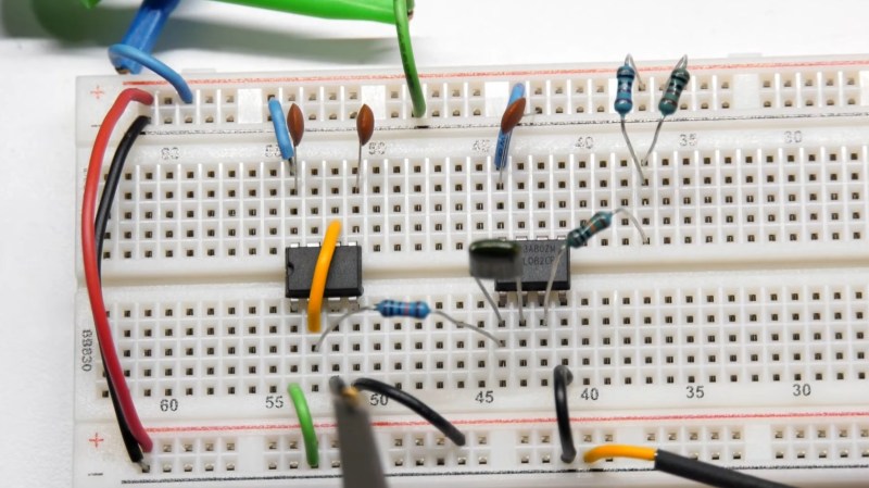
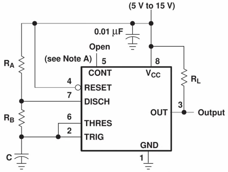 As beginner videos go this one is fairly comprehensive. [Andrew] shows us how to build a square-wave generator on a breadboard using a 555 timer, explaining how its internal flip-flop is controlled by added resistance and capacitance to become a relaxation oscillator. He shows how to couple a potentiometer to vary the frequency.
He then adds an integrator built from a TL082 dual op amp to convert the circuit to a triangle-wave generator, using its second op amp to build a binary inverter. He notes that a binary inverter is usually implemented with a comparator, but he uses the op amp because it was spare and could be put to good use. Again, potentiometers are added for frequency control, in this case a 1 MΩ pot for coarse control and a 10 kΩ pot for fine control. He ends with a challenge to the viewer: how can this circuit be modified to be a sine-wave generator? Sound off in the comments if you have some ideas!
If you’re interested to know more about function generators check out A Function Generator From The Past and Budget Brilliance: DHO800 Function Generator.


The Falstad circuit simulator already includes an example of a triangle voltage controlled oscillator. It’s basically the same thing as what’s used in this video. (Menu: Circuits/Op-amps/Oscillators/Triangle VCO) In that circuit, one of the op-amps is used as an inverting schmitt-trigger. A common modification on that example is replacing this op-amp with a 555 because it’s faster at switching.
The fundamental problem of the example circuit is that op-amps are slow to “turn around” and flip the output from high to low. As the frequency goes up, the integrator will shoot past the set voltage before the inverter can react and the amplitude changes. The VCO acts non-linearly in respect to the control voltage because it takes a larger swing at higher frequencies, which is not something you usually want to have.
With another 555 instead of an op-amp, you have an Atari Punk Console (or Stepped Tone Generator if you learned it from Forrest Mims first!) You also get the advantage of two points of voltage control which, while crude, are fun.
Can’t you just use a Wien Bridge circuit to filter the oscillator into a (simulated) sine?
I’m not exactly sure how you would, but there’s another way: If you have a constant amplitude triangle wave, you can pass it through a slightly modified diode log amplifier and get a very close approximation of a sine.
The circuit is virtually identical to some versions of the Fuzz effect pedal, where you have two opposing diodes and a resistor in parallel in the feedback path of an inverting op-amp. You’re basically dialing it in between the linear resistor-resistor path and the logarithmic resistor-diode path by trimming the resistor. When you push it louder, the triangle turns into a sine first, and then into a rounded square wave, so you’re just gonna fiddle it up and down and listen when it plays the cleanest, and that’s your sine wave.
If you DC-couple the signal into the amplifier, and then shift the ground reference up or down, you can do asymmetric sine-triangle, or square-sine, which is going to sound brassy or violin-like, etc. Modulate it with an LFO to get weird effects…
The setup is sensitive to temperature and starts to leak through the inherent capacitance of the diodes at higher frequencies – but that’s fine if you’re just playing some tunes and don’t need a mathematically exact waveform. Your ear can’t tell the difference between a sine and a slightly triangular sine at higher frequencies, because the harmonic distortion goes above your hearing range, and you’re not going to be playing notes that high anyway.
I don’t recall what chip was used, but as a university assignment back in the mid-90s I had to build a square/triangle/sine function generator using a particular chip that did most of the work. It did exactly this. According to the datasheet for the chip, it generated a triangle wave (very much like the 555-based circuit in this article), and then the square wave was a by-product of this because it was just the comparator output, and for the sine wave, it used a multi-stage diode network that rounded off the tops of the triangle waves by shunting more of the signal to ground as the amplitude increased. In fact, you could SEE on a ‘scope that when you switched from triangle to sine mode, the waveforms were identical aside from the tops being rounded off.
It may have been an Exar XR-2206 (datasheet here https://www.jameco.com/Jameco/Products/ProdDS/34972.pdf), and if not, it was something virtually identical to that.
That’s the brute force way to do it. See Falstad example Circuits/Diodes/Triangle-to-Sine Converter. It’s implementing the same effect by a resistor ladder that creates a sort of piecewise linear function and the diodes just switch different parts of it in and out of circuit. It works, but it’s also incredibly fiddly to get all the resistor values right. The benefit is that you can work with bigger signal amplitudes and avoid noise.
For the diode log amplifier “Fuzz converter”, if you want more amplitude than +/- one diode drop, you can simply add more diodes in series, like this:
https://tinyurl.com/27eklcj6
The temperature dependence is about 2 mV per K per diode, so for this particular setup the correct trim shifts roughly 0.25% per degree. Even if you tune it just right and you play it for a while, it’ll drift and introduce a little bit of harmonic distortion. You could compensate by adding just the right NTC/PTC resistor that offsets the error around room temperature, but since you’re going to be tuning it by ear anyways, that hardly matters.
If you look at a sine function around zero degrees, you can approximate it by a straight line. Sin(X) = X. The error remains less than 0.5% up to +/- 10 degrees. Going beyond, if you plot the difference X – sin(X) for the first quarter of the cycle, what does the error function look like? It looks like an exponential function.
That’s why the log amp trick works – it’s not the exact inverse function but it’s got the same shape, or close enough. Introduce the opposite error and it cancels out.
Could have done that with a 555… or wait… :D
Did you see how CuriousMarc got a bit testy when people pointed out an OpAmp he used was a bit dated? And that was the TL092 I think.
But I’m guessing people making videos like this probably just got book from 1982 or something about the 555 and are recreating what they read there and using the part therein.
Reminds me of GreatScott making a video about the electrical system and clearly using some UK information source and not realizing in his own Germany and in the rest of the EU things are laid out differently with a different history.