There are many adapters, dongles, and cables designed for interfacing display standards, and no doubt some of you have them in the glue of your entertainment system or work space. They’re great for standards, but what about something that’s not quite standard? [Stephen] has an arcade cabinet with a CRT that runs at an unusual 336 by 262 pixel resolution. It can be driven as 320 by 240 but doesn’t look great, and even that “standard” resolution isn’t supported by many dongles. He’s shared the story of his path to a unique USB to VGA converter which may have application far beyond this arcade machine.
We follow him on a path of discovery, through RP2040 PIOs, simple resistor ladder DACs, and home-made kernel modules, before he arrives at GUD, a USB display protocol with its own upstreamed Linux kernel driver. It’s designed to be used with a Raspberry PI deriving an LCD or HDMI display, but for his task he implemented the protocol on one of the more expensive STM32 series microcontrollers. The result after several false starts and some fiendish PCB routing is a standalone GUD-based USB-to-VGA converter that delivers perfect 34-bit colour at this unusual resolution, and also presumably others if required. It’s a worthwhile read for the many hints it gives on the subject of driving displays, even if you’re not driving an odd cabinet monitor.


“… standalone GUD-based USB-to-VGA converter that delivers perfect 34-bit colour at this unusual resolution …”
I think you mean 24-bit colour.
Also, “It’s designed to be used with a Raspberry PI deriving an LCD or HDMI display…”
Should probably be “…driving an LCD…”
If It’s for arcade cabinets, low latency is critical.
Looks great – but resistor DAC directly connected to output? No buffers? It looks like it works but still, 3 video opamps are not that expensive or large.
So if they want to eventually use a laptop to drive the display, why not just get one with a VGA port and configure it to the desired resolution and refresh rate? I’m not quite understanding why it had to be over USB.
Lots of things with VGA ports can’t draw a sufficiently low pixel clock. At best, most support the same original 12.6MHz that the original VGA card used for its low resolution modes, but this needs 6.4MHz.
The only graphics card I ever encountered that supported lower pixel clocks was Matrox’s G200/400/450, which has a register to optionally divide the pixel clock by 2 or 4.
Apparently, I’m behind the times. It used to be that all GPUs/graphics cards could support NTSC rate output, but it seems like that’s been abandoned with more recent GPUs. These days, the typical solution is a rescan device. There seems to be a wiki page about this:
https://www.aliexpress.com/p/wiki/article.html?keywords=crt-15khz
All those Aliexpress wiki pages appear to be AI generated (or some kind of weird reconstitution of existing articles for the like 2 I’ve seen that are pre-AI)
Me wonders why they don’t use a FL2000 based USB-to-VGA converter. These can be programmed to output arbitrary signals:
https://osmocom.org/projects/osmo-fl2k/wiki
CRTs dont have pixels or exact horizontal resolutions :) Its ordinary 15.7kHz CRT, 240 visible lines. Previously they ran it with Gert vga666 set to 240 visible + porches = 262 https://www.frankchiarulli.com/blog/building-the-rcade/
Article:
but he doesnt use hyperbus
there is SDRAM on board, but memory.x says its not used at all
this micro has 1MB of SRAM so no external ram would be needed anyway at those small framebuffer sizes
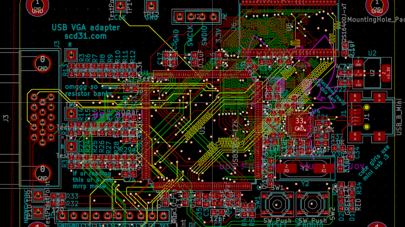
Looking at PCB:
huge cuts in ground plane right across Ram address/data bus, good thing he doesnt use this ram at all :)
whole PCB ground plane is cut in half by ram and VGA routed in the ground layer :o
0.3 hole 0.4 diameter VIAs have extremely small annular ring, afaik very bad idea leading to manufacturing/reliability problems. I am guessing author tried to make small clearance VIAs but instead broke them while leaving huge (0.5mm) clearances overridden by GND/Power plane settings. Those settings arent entirely obvious and one might give up trying to find what is locking clearances.
usb impedance mismatch, but meh its short
usb differential impedance mismach is bad with one DM crossing thru two vias, length mismatch by ~120mils
bypass cap right along USB High speed track also not good
all usb ULPI signals going over huge ground hole no bueno
Length matching (up to 10mm margin) will be less important on 60MHz ULPI than crosstalk between 4mil tracks routed with just 4mil clearance without solid ground underneath.
Im loving the can do plowing thru obstacles attitude. Author got there in the end and made working solution to his initial problem.