Sometimes you’re looking for a component for a project that you know should exist, but you just cannot find it. Something like a 14-segment LED display, but not just one with a fixed color, instead you want some of that sweet addressable RGB-ness. Unfortunately for [EastMakes], this particular display was nowhere to be found, so he decided to try making his own.
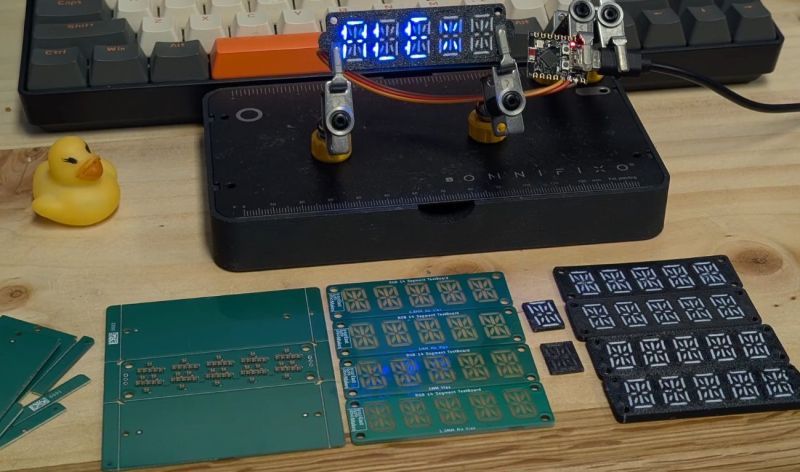
Using addressable SK6805 RGB LEDs with a mere 1.5 x 1.5 footprint as the basis, the layout for these individual LEDs on the PCBs was determined, and a layout created in KiCad. The PCB manufacturing and assembly were straightforward enough — the thing that really makes these displays is the diffuser. Here a few different approaches were tried, including FR4 with translucent segments in the soldermask, and a 3D printed version in both white and black PLA filament.
The FR4 approach using 0.8 mm thin PCBs looked quite all right, with the addition of through vias in the 1 mm version showing how these help to boost overall brightness. The 3D printed version prototypes didn’t look too shabby either, but it would probably help a lot if this diffuser panel also fit around the LEDs to prevent light bleeding between segments.
We’d love to see this type of RGB display being experimented with, as it seems to hold a lot of promise while also definitely being something that ought to exist.


“The world first” is a ridiculous overstatement, stupid clickbait titles ….
The idea itself has been done numerous times and always the same shine-through problem ….
I wonder why nobody ever tried it with reverse mounted led´s…..
Time to start a new experiment.
The issue with most LED segment displays is the size of the partitions between segments, and this one is no different. It’s one reason why LCD is often preferred. If someone could find a way to decrease the gaps while still being 3D printable, that would be quite something.
Maybe use a projection system or a shadow mask to cast the segments onto a screen. Even a slight gap between the partitions and the front diffuser would spread the light wider than the aperture.
Damn you are right. I thought i could be a smartass but even with reverse LED´s shining through the FR4 there will always be reflections shining through the other segments no matter what because of the thickness of the material ….
The LEDs used have a 1.5mm width x 0.65mm height. So would mounting them sideways inside the pcb might be an option?
I’ve never designed a pcb- but couldn’t you add rectangular cuts in the pcb and slot the led into the cutout. There will be 2 pads on each side of the pcb per led. Manually add solder to the pins – which maybe made much easier due to the pcb holding the led in place for you. Make sure pcb thickness is less than 1.5mm so each led pad can be within reach.
The light would go out the side of the led and the space between each segment is now much greater perhaps allowing you to 3d print walls thick enough to block light from neighboring segments.
Again – not a pcb designer.. so maybe there would be some cool tricks to prevent the light which is now directly pointed into the layers of the pcb from leaking to neighboring segments? Or somehow blacking out the tops of the segments before you install them?
OMG nice one, congrats!
it seems we had the same idea around the same time. here’s my take on it, the digitus16:
https://codeberg.org/wenzellabs/digitus16
and a first application is blonkenclick (blinkenclock was taken):
https://codeberg.org/wenzellabs/blonkenclick
it’ll be in my lectronz shop very soon, just waiting for 3d-prints and better photos =)
I also experimented with PCB material as diffusor, but I dumped the idea. simply has too much color bleeding from neighbour segments. also note I placed all LEDs in the same orientation. this way the colors are more consistent from one viewing angle. the R, G and B chips are not in the same position on the 2mm x 2mm package which makes the observed color angle-dependent.
you may want to have a look at my digitus16 micropython library. grab what you can use, or maybe even better we manage to benefit both from having one library to rule them all. at the moment we diverge quite a bit, 16 segments vs 14 segments, and SPI-based chips vs single wire. don’t miss my rant on WS2812B on the bottom of the README ;)
cheers
IMHO, neat trick, and I second 3-d printing of these.
A decade ago I needed a quick-working imitation of 7-segment run by Arduino Nano, and being rather short on time to wait for the mail order (I only had that many man-hours to spare during a random lull between family obligations’ tall list of Tasks To Do Now), I hacked a hot-glued one from white foam presentation board spares I had laying around. I literally cut out segments’ cavities with exacto knife and fit LEDs to shine sideways (LEDs were sanded so that they’ll dissipate the light kind of sort of flooding the segment – not very bright light, but enough to have the kind to shine at night). Long story short, it was kind of neat to see it light up and not bleed over between segments too badly, and since it was white, it appeared as one solid surface with magical segments shining through : – ]
I never went though the rest, adding things I wanted (date, etc), so it kinda lingered in the drawer until last years’ spring cleanup and was discarded. The idea there was to make is as cheap as possible using available resources, and now that I think of it, I should have invested into CriCut and tune it for foam cutting, just never had a real need or any projects that would require cutting things on semi-industrial scale : – ]
You know, some strategically-placed vias between segments could go a long way in mitigating bleed-through.
Though, so would using something better than a thick slab of FR4 for the task.
A resin printer would work a lot better for this. FDM just doesn’t have the resolution to print small displays.
it seems we had the same idea around the same time. here’s my take on it, the digitus16:
https://codeberg.org/wenzellabs/digitus16
and a first application is blonkenclick (blinkenclock was taken):
https://codeberg.org/wenzellabs/blonkenclick
I also experimented with PCB material as diffusor, but I dumped the idea. simply has too much color bleeding from neighbour segments. also note I placed all LEDs in the same orientation. this way the colors are more consistent from one viewing angle. the R, G and B chips are not in the same position on the 2mm x 2mm package which makes the observed color angle-dependent.
you may want to have a look at my digitus16 micropython library. grab what you can use, or maybe even better we manage to benefit both from having one library to rule them all. at the moment we diverge quite a bit, 16 segments vs 14 segments, and SPI-based chips vs single wire. don’t miss my rant on WS2812B on the bottom of the README ;)
happy hacking!
I’d use a black PCB for the middle slice.