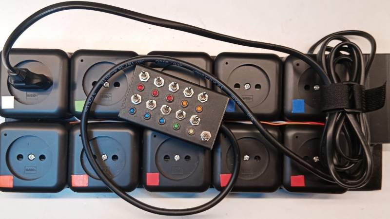
Who among us does not have a plethora of mains-powered devices on their workbench, and a consequent mess of power strips to run them all? [Jeroen Brinkman] made his more controllable with a multi-way switch box.
At first sight it’s a bank of toggle switches, one for each socket. But this is far more than a wiring job, because of course there are a couple of microcontrollers involved, and each of those switches ultimately controls a relay. There are also status LEDs for each socket, and a master switch to bring them all down. Arduino code is provided, so you can build one too if you want to.
We like the idea of a handy power strip controller, and especially the master switch with the inherent state memory provided by the switches. This could find a home on a Hackaday bench, and we suspect on many others too. It’s by no means the first power strip with brains we’ve seen, but most others have been aimed at the home instead.


>talks about workbench
>uses non-earthed sockets that were already obsolete 30 years ago (unless you live in one of the CIS countries where TN-S is still a luxury)
https://www.geekalerts.com/u/picard-facepalm.jpg
The person who made this has the most Dutch name ever. So that would be a TN-C-S system if he’s indeed Dutch.
This is the first time I heard of CIS countries. Eurasian union. Interesting.
I think the term was created right after the fall of the Soviet Union. Ex-Soviet countries banded together to go to the olympics and deal with common issues.
Oh now it rings a bell – it looked like i saw these sockets somewhere, but was’t able to remember where. Because they are black. In Russia, if this type is used, it is almost always made from off white brittle plastic – like this one https://www.etsy.com/listing/862968067/vintage-ussr-electric-outlet-retro-white
There were (still are) also appliances with plugs from same off white plastic – but instead of just flat two prongs as we know from Europe (Europlug), they had round flange. And no hole for grounding pin (GOST 7396 C1 – https://en.wikipedia.org/wiki/GOST_7396#/media/File:Soviet_Plug_Type1_6A_250V.jpg) . So they can somehow be forced into shuko but not type E.
We had the same plugs with the same brittle plastic in the Netherlands. I’ve used saws and files to cut the holes for the ground plugs in the sides of the round connectors because the round connects did not have any cutouts for grounding pins. I have outlets in my house that are also just round with no grounding pins, and are made from Bakelite.
So I guess the old Dutch and USSR electrical outlets and plugs are the same or at least very similar
The Netherlands has a large amount of buildings that were wired using old conventions and has not made it mandatory for full-scale rewiring unless it is actually hazardous. One of these being that grounding was only mandatory for high-power devices such as Kitchen appliances, washing machines and the Central-heating boiler.
Because of this a lot of rooms in buildings that weren’t built in the last few decades: lack grounding cables and because it is considered more dangerous to have a socket with grounding pins that isn’t actually grounded than one that is openly not-grounded: It is still possible to buy/use sockets without them.
For my own house i said “Nope” and went through the trouble of pulling that green-yellow cable all over the place and replace all the sockets.
I hear China also does not use grounded outlets for normal household stuff, and Japan also has an odd mix.
In my house they also don’t use grounded outlets in living/bed rooms.
(Admittedly I did add a few myself with grounding, because of interference reasons.)
And as for the snark: I hear tons of homes in the US have grounded outlets where there is no ground connection internally. I’d rather know than think wrong myself.
Addendum: I agree that if you build a thing like this yourself for a specific use it would make sense to use grounded outlets.
You’d only need one line to ground for the whole lot and it would not be switched, so it’s not too much of an extra effort.
Incidentally central heating if using metal tubes is connected to ground, might help you find a grounding block nearby to run the wire to if you have central heating. Or you can connect a ground wire to central heating as a tap, but that is not up to code.
I would have just used a row of light switches and receptacles, with one switch as a master, but this does make the control box smaller.
I think the other thing is the control box it’s a low voltage. But I think that the same thing could be obtained using a 24 VAC transformer and relays, and an RCD as a master switch.
I think 12V^(DC) relays would be much safer because there’s no risk from ungrounded earth connection like in AC setup.
The American DJ SR P8 would be great for this in the US…or any other country that uses that style outlet (Japan for example). The DB9 connector uses 1 pin for common ground. Supply 12vdc to the other pins to turn outlets on/off.
DE-9 …
This looks like a hell soldering job for what it is… and with the 2 amp relays and unearthed outlets I wonder what it might be useful for?
Pure inspiration is the purpose:)
USB power bricks and lights would be my guess.
A dremel(-clone), uses less than 200 watts and is fully isolated electrically and needs no ground.
And a main powered glue gun maybe.
And 12V power bricks for a few technical devices and gadgets.
And power tool chargers.
Seems there are more things than I initially thought of too :)
Why the microcontroller other than… just because? The switches could control relays directly and be a lot simpler.
It looks like the microcontroller is just used to reduce the number of wires in the control cable. Connecting the switches directly would have needed a cable with 11 conductors.
In the US:
https://www.amazon.com/Kasa-Smart-Power-Strip-TP-Link/dp/B07G95FFN3
Individual outlet control, with energy monitoring, code available to access it without their app, even HomeAssistant can connect to it, etc.
So?
So, the cost of materials and time, for the solution presented in the article, is not a worthwhile solution, unless you just want to make something for the experience – and even then, the experience has a cost as well.
Maybe you should check out “buyaday.com”?
… wasteaday.com for you, then?
Life is short. Everyone has a threshold where they decide whether to do a thing themselves (if it’s possible), or pay someone else to do a thing. If the time to do a thing yourself is worth more to you than simply paying for a thing (value of finished result, value of what may or may not be learned from the effort, quality of the result, on and on), what do you do?
For many / most things we buy, economy of scale wins, outright. What we get as an immediate result for purchasing those things is time, time to do things we find of greater value – and that value may include cost beyond financial cost.
I cannot count the number of projects I’ve spent more time and money on than if I’d just bough tit new. It’s what we do. 🤷♂️
I get that, I do – and I understand in many ways how one can invest to a point where one feels a need to see a thing to the end. I get that.
For this project, there is a risk here: if you set your house on fire, there’s liability. The power strip I referenced, I looked specifically for IoT things that had UL approval, as there are many sketchy things on the market that can and do cause fires.
It’s power distribution, not much to be inventive about there. And while the project mentions utility of the remote switch panel, I can pull up my Kasa things, like my power strips, on my phone when I’m at home (local access only in my setup), and check and switch on or off sitting on my couch. I could build such a thing, but the cost, and risk in this case, isn’t worth it.
Often, I’ll have an idea, research, find someone has built such a thing, and buy it. If I can’t find a thing, or can build cheaper than buy, or want a feature I can’t buy, I then consider what it’ll take to DIY. If DIY isn’t worth estimated time and cost, I won’t bother. Sometimes I’ll get to a point in some effort, consider time spent, and realize I underestimated the cost / overestimated the value of a thing, and move on, no emotional attachment, no addiction to chasing an elusive solution.
An effort has to make sense, on some level. I understand art-like efforts, I understand some just aren’t attached to the notion of ROI for their hobbies and carry on “for fun”, but for me, any project has to have meaningful value when complete. Otherwise, I’m taking time from things that offer greater value.
I typically pick a project specifically based on having maximum value for time invested. I do the same in my day job. I never have enough time, so I focus on best use of the time I have available.
That said, there are a lot of ways to quantify value – but I can’t make sense of build instead of buy to control AC power like this.
Here in the UK mains outlets with individual switches and lights are readily available. The shape of UK plugs (flat back) makes it easy to label them. I have a giant 60A switch to isolate everything that is very satisfying to throw.
there’s simpler ways to do this and there’s off the shelf products that really do what you want much more reliably and that put my finger on why i object to this: the last thing you want to do at your workbench is debug the electrical receptacles. at the work bench, i want my tools to work so failures in my prototype are more apparent. there’s a few specific times you want automated power off on your workbench (like recovering data from a hard disk that needs a power cycle to progress) and those are better off addressed specifically than having some complicated box between your power and every experiment.
that’s my two cents :)
You “object” to someone making a project you don’t like, or because there’s an off-the-shelf alternative? Who are you to “object”, rather than “opine”?
If someone wanted to do this same project, but instead maybe cobble together their own outlets from bits of metal and 3d printed parts, and perhaps their own relays with hand-wound coils, or maybe their own microcontroller from discrete components, and why not, their own wire, at what point is the effort … no longer viable for time invested?
I’d rather focus my mind on problems not yet solved, or solved with features not available elsewhere, or available significantly cheaper by DIY.
Seems to me like you have no problem focusing your mind and wasting your time on wining about people creating stuff.
Why don’t you go solve problems that have not yet been solved instead of complaining in the comments?
You’re so sweet, Burt. You’ve inspired me, not to engage, but to leave.
i’m the peanut gallery making my own judgement i’m sorry
I can’t recall the brand now, but I have an (old) 8 outlet power distribution strip controlled by RS232.
I was able to find the protocol and fiddle with it hoping to use it as a sequencer for Christmas lights. Alas, it seemed to have some denounce built in so was way too slow for what I wanted. It has been happily powering up my main PC desk for years now with all relays set to the On state. Still pops into my head occasionally that I should build a controller from an Arduino or something and move it to my electronics workbench or retro gaming area.
Excellent idea, and I’ve seen something similar before.
In my garage we’ve added simple lighted switches (each switch has a neon bulb inside, so it will take some long while for them to eventually fade out) serving about the same purpose. A glance at the switch from across the garage will tell you if it is on or off. We went with the simpler system, two power outlets and two switches above them, and they are placed strategically, ie everywhere, so at any time you are only one extension cord away from a nearest switched power outlet. There also a master switch, no neon bulb, to shutdown entire enchilada when leaving for the day. Oh, and this summer we will be adding the ceiling power outlets as well, with the retractable cords, same story, will be adding lighted switches somewhere near, maybe on the ceiling (this an old garage with low ceilings).
Solid-state relays, mmm, in the past I bought few and found out they are barely holding what they are rated for, so I’d rather have old school mechanical thing that’s known to Just Work. Actually, with the US switches that are protruding out of the box, one can probably 3D print small solenoids to push these on/off using some benign voltage, 12v or even 5v, just I am too lazy : [