
A well-known property of wall warts like power bricks and USB chargers is that they always consume some amount of power even when there’s no connected device drawing power from them. This feels rather wasteful when you have a gaggle of USB chargers constantly plugged in, especially on a nation-sized scale. This is where a new USB-C wall charger by Belkin, the BoostCharger Pro, is interesting, as it claims ‘zero standby power’, which sounds pretty boastful and rather suspect. Fortunately, [Denki Otaku] saw fit to put one to the test and even tear one down to inspect the work of Belkin’s engineers.
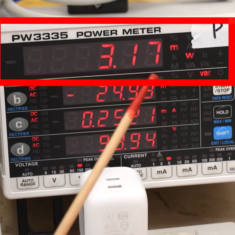
Naturally, no laws of physics were harmed in the construction of the device, as ‘zero standby power’ translated from marketing speak simply means ‘very low standby power usage’, or about 3 milliwatt with 0.3 mA at the applied 100 VAC.
Fascinatingly, plugging in an e-marker equipped USB-C cable with no device on the other end caused this standby usage to increase to about 30 mW, clearly disabling the ‘zero standby’ feature. With that detail noted, it was time to tear down the charger, revealing its four PCBs.
The boring answer here is that Belkin didn’t do anything special, but rather followed the Renesas application note for a 65W USB-C adapter with Zero Standby Power:
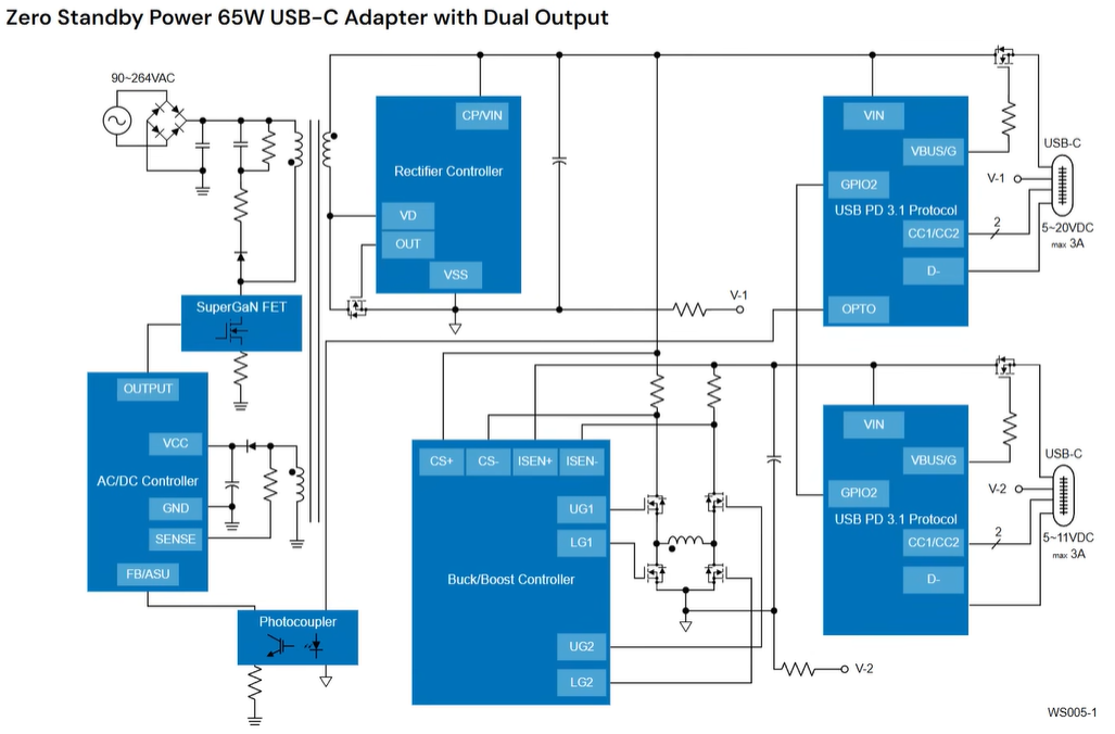
As can be surmised from the effect of a non-e-marked versus e-marked USB-C cable being inserted, the USB-PD controller IC detects the presence or absence of a cable, and signals the flyback section to mostly shut down. This then leaves a trickle of current for the charger’s ICs as they wait for something to happen. In the (unfortunately restricted) datasheet for the Renesas iW9870 flyback controller IC, we can see this feature described, including how plugging in a USB cable disables the feature.
This feature appears to be somewhat related to how USB power banks work, with them shutting down the outputs if idle, though there are some issues with it backfiring. Some power banks have a ‘trickle charge’ mode where even low amounts of current being drawn doesn’t shut off the output. In the case of this Renesas ‘zero standby power’ feature, it seems to rely on USB cable detection as an equivalent to an active power device.
As noted in the video, this seems to cause issues when inserting an e-marked cable, and some users have reported the charger randomly turning off the output while actively charging from it. Here we’d like to pitch an absolutely bonkers suggestion, and pitch putting a physical on/off switch on the charger – as well as on power banks – rather than try to do more smart guessing.


My back-of-the-envelope way of calculating the yearly costs of such a stand-by device is:
1 Watt stand-by power costs about 1 Euro per year
A device like this, consuming only 3 mW in stand-by mode, costs less than one Eurocent per year and, at that price point, you’re better of leaving it in the wall socket constantly as even those sockets only last a limited number of insert-remove operations.
Or, you’re better off leaving it on the store shelf as it’s likely to cost enough extra to completely offset the savings versus some generic cheap charger.
If a cheap charger costs 15 euros and the Belkin unit costs €30 then it has chance of making the money back in “only” 15 years, at which point the whole charging standard will have changed and/or the device has broken down anyhow.
Not forgetting to factor in the cost of that fancy ~ £2,000 power meter!
It’s really 30mW though, because who leaves a charger plugged in without a charge cable attached to it?
So, uh, 30¢…
For a non-permanent installation this is 100% correct. If this were applied to an outlet that also provided USB outlets to plug in a cable then it would qualify it as 3mW.
Your conversion is wrong. If 1W is 1€ then 30mW = 0,03W is 3 cents.
However 1W = 1€ does not hold in Germany (and many other European countries) anyways. 1W is 8.76kWh per year. At 0.25€/kWh (my current price) that is 2.19€.
Nah, that’s largely just Germany, where 60% of the power price is taxes and regulatory fees, and other “redistribution”.
E.g. large industry consumers pay no grid fees, and the cost is distributed onto the consumers by the Federal Network Agency who sets the transmission prices. That’s a Reverse-Robin-Hood subsidy from the poor to the big corporations.
Back in the day, I put a few chargers into an extension socket on a simple timer so for things like phones and pads that charged up over night. The extension was only on for 6 to 8 hours overnight when the chargers were needed.
I have a couple of Belkin extension cords that came with a remote switch – tap it and the thing powers on for ~8 hours or until you tap it again, whichever is sooner. Very useful for the soldering irons etc. in the shed as you know they’ll never be left running.
One note of the video. It’s showing 3 milliWatts of real power, but 30 milliwatts of var which suggests a power factor of about 0.1 which is quite terrible if a lot of these devices are connected to the power grid.
This is reactive power that is not billed from the user, but it still increases the current demands on the network and causes other issues like EMI. However, adding power factor compensation and filtering on the input of the charger would increase cost and lower the efficiency, and increase the idle power draw somewhat so they couldn’t advertise it as “zero standby”.
For the amount of reactive power they take at standby, I am assuming the parasitic capacitance of the transmission lines has to be enough to counteract that. Its tiny! At full blast though, yeah its not very good for the grid
Looking at the circuit diagram, the reactive power is probably just the rectifier and the first capacitor. The reactive power is the ripple of the input capacitor that leaks through to the AC side. Every time the AC voltage goes above the capacitor voltage, you have a sudden rush of current into it, so there should be a filter before the rectifier or else it’s just going to have a terrible power factor.
If I simulate the circuit, I get an inrush current of almost 4 Amps, which is the reason why these things tend to go “snap” when you plug them into the socket. Then for a 0.25 mA load I get short peaks of 9-10 mA from the AC source. These sub-millisecond spikes then propagate back through the house wiring and into other devices. Old style wall warts didn’t have this issue because they had a step-down transformer before the rectifier to act as ballast – but of course they were not as efficient and took more space.
These things are individually not a problem, but when you have a house full of such non-compensated devices – like every LED bulb or every small appliance that has to have a USB-C connector for power these days – it becomes a power quality problem. The noise interferes with things like ground fault interrupters and causes issues in other devices, like adding high frequency ripple to the capacitors in the regulators of your LED bulbs, which then heat up and break down sooner.
I assume 30mW of reactive power isn’t enough to bother the power grid. If it’s capacitive reactance, it helps offset the inductive reactance from motors, etc.
Except motors are no longer inductive because they’re driven by VFD inverters, which have huge capacitors on the input side.
Even microwave ovens are now running the magnetron on an inverter instead of just chopping it on and off like they used to. Pretty much everything has a switching power supply now.
hum.. typo?
doesn’t compute:
“or about 3 milliwatt with 0.3 mA at the applied 100 VAC”
It’s real, but imaginary. Or rather, complex.
That’s what you get when you’re a reactive load.
The current is real, the power is real, but the reactance is very real, so the power factor is awful.
(Never mind that the author didn’t make that apparent in that statement.)
What this tells me is that the “Renesas iW9870 flyback controller IC” should be what they use in permanent electrical outlet installations that also provide USB-PD.
While I’m generally opposed to the idea of installations that are always consuming power, not only do they already exist but it’s also a better option than people leaving USB-PD adapter plugged in, which even I’m guilty of doing on occasion.
So taking the worst one at 178mW that equates to 235 days to burn a single KWH at roughly 25p. Not exactly a big concern.
Couldn’t the physical switch be spring loaded inside the USB port so when the USB plug goes in it switches on and when it comes out it switches itself off?
I played around with this idea a while back with a carefully arranged USB-A port, tact switch, spring and a bit of acrylic rod.
It worked quite well when it was all aligned right, but wasn’t worth the trouble to manually set up for a real project.
However, if a manufacturer could figure something out, even something like a switch contact as used in SD Card sockets, that would be great.
What about people who never remove wire used for connecting charger and the USB compliant device from the socket. A case such as mentioned in previous sentence is very well known to phenomenize https://www.usb.org/sites/default/files/usb_20_20250603.zip