Although not really a cost-effective or a required skill unless you have some very specific needs not met by off-the-shelf power resistor options, making your own own wirewound power resistor is definitely educational, as well as a fascinating look at a common part that few people spare a thought on. Cue [TheElectronBench]’s video tutorial on how to make one of these components from scratch.
The resistance value is determined by the length of nichrome wire, which is an alloy of nickel and chromium (NiCr) with a resistivity of around 1.12 µΩ/m. It’s also extremely durable when heated, as it forms a protective outer layer of chromium oxide. This makes it suitable for very high power levels, but also requires the rest of the power resistor assembly to be able to take a similar punishment.
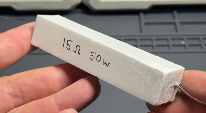
For the inner tube of this DIY power resistor a tube of alumina ceramic was used, around which the nichrome wire is wound. This resistor targets 15 Ohm at a maximum load of 50 Watt, this means a current of about 1.83 A is expected at 27.4 V. The used nichrome wire has a measured resistance of 10.4 Ohm, ergo 1.44 meter has to be cut and wound.
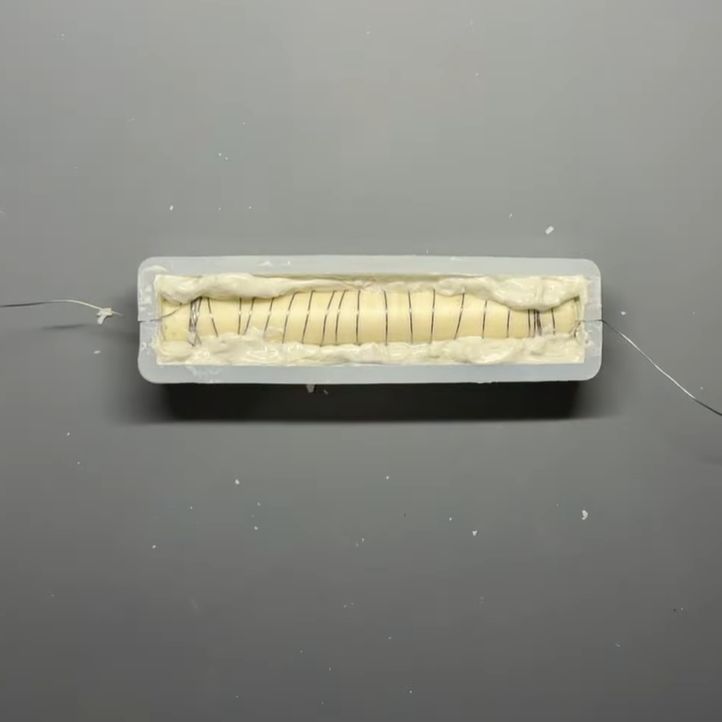 This entire assembly is then embedded in refractory cement (fireproof cement), as this will keep the wire in place, while also able to take the intense temperature cycling during operation. As a bonus this will prevent toasting the surrounding environment too much, never mind lighting things on fire as the nichrome wire heats up.
As explained in the video, this is hardly the only way to create such a power resistor, with multiple types of alternative alloys available, different cores to wind around and various options to embed the assembly. The demonstrated method is however one that should give solid results and be well within the capabilities and budget of a hobbyist.
An important point with nichrome is that you cannot really solder to it, so you’ll need something along the lines of a mechanical (crimping) connection. There are also different winding methods that can affect the inductance of the resistor, since this type of resistor is by its design also a coil. This is however not covered in the video as for most applications it’s not an issue.
Overall, this video tutorial would seem to be a solid introduction to nichrome power resistors, including coverage of many issues you may encounter along the way. Feel free to sound off in the comment section with your own experiences with power resistors, especially if you made them as well.


Manganin wire, while a little more expensive, is also good for wire wound resistors. It has very good temperature coefficient and stability.
I’m currently waiting on delivery of a spool to rewind a Yokogawa 1Kohm standard resistor.
The older high value ones tend to corrode the wires where they are soldered due to decades of humidity.
I’ll rewind the entire resistor using the same bifilliar wind, and ‘tune’ the resistance on my 3458A multimeter.
Most of the old manganin wire is still good, only the ends were corroded, so it’ll be kept for future projects.
That µΩ/m book conductivity to Ω/m wire length conversion is a weird conversion. Had me for a moment.
There is a typo in the quoted resistivity as it should have a unit of µΩ * m
Just encase it in plaster of paris or white cement. No need to over complicate this
Yeah, if your resistor is reaching temperatures where refractory cement and alumina are necessary ingredients, then you’ve done something very wrong. Plaster is good to 1000C, at which point your resistor would be glowing fairly brightly.
But keep in mind that the plaster will start releasing it’s chemically bond water at around 120°. It’ll probably probably become conductive. https://en.wikipedia.org/wiki/Plaster#Gypsum_plaster
When it’s lost it’s water it’ll be very hygroscopic.
It won’t crumble back to powder but it’s probably not as strong.
Ideally the outer shell of the resistor won’t get that hot, but even if it does, cooked plaster is still strong enough to hold itself together. Resistors aren’t structural, for the most part. Also, plaster is conductive when waterlogged, but otherwise has a resistance in the megohms for most small parts. It’s basically the mineral equivalent of wood. They used to use it to cement the bases onto lightbulbs, and it worked well for that.
Surely the resistivity is dependent upon the GAUGE of the wire as well.
Yes, it is. The resistivity is calculated as rho = R * A / L, where rho = resistivity, R = resistance, A = cross-sectional area, L = length. The units given above are incorrect, due to the area figuring in.
I worked for a couple of years for a power resistor company in Manchester, NH. I made a lot of the controls and production machines to help the ladies on the production floor with more ergonomic and reliable equipment. When making 1% or better resistors, the usual method was to watch a precision meter and gently apply fine sandpaper to the spinning resistor. The resistor was made with a slightly low value to start and the abrasive cloth would raise the value to what was needed. We also made low inductive resistors that would have two sections to the bobbin. Each section was wound in a different direction to cancel out (to a degree) that the customer specified. We made high precision, high current parts for Fluke for their multimeters. Kelvin 4 wire connections, of course.
Another interesting part was made with nickel wire for temperature sensors for solar systems. 1000 ohms typical. Very reliable and low drift after years of use. My system has run for over 35 years without problems.
The ladies on the production floor did this job for years. One, who retired was given the machine she had run for years. It was given a proud space in her home. Some spoke French as a first language and had never left the city neighborhood where they grew up. If I had any questions, they were my first source for the right answers.
I distinctly remember the perplexing ah-ha moment when working on my first 3d printer to learn that the most popular heating element design was literally a standard through-hole resistor run at much higher current than its rated capacity. It was bonded with thermal paste to an aluminum block “heat sink” that was attached to a nozzle.
I’d known all along that a resistor and an electric heater were exactly the same thing, but it didn’t quite sink in until I saw them used interchangeably.
Nowadays they replace the cheapo resistor with a “heating cartridge.” Basically still just a resistor, but with a metal casing instead of a ceramic one.
Constantan wire has the advantage over Nichrome of being solderable. That makes it quite a bit easier to use for making reliable resistors. Mine has seen plenty of use making low value Rs over the years. Good to snaffle when you see a roll somewhere.
Years ago one of my designs was copied by a company who failed to understand that the wire “jumper” (current sensor) was not wire. They had no engineers and had simply sent my board out to an assembler to be copied. 5000 boards that burnt up motors out in the field when the motor had a stall load, which would be all of them within a year or so. They blamed the assemblers of course.
The ceramic tube he is using is hollow. It looks to me like he isn’t filling the inside with cement, but just covering the sides.
That would mean there is quite some air trapped inside that will expand when heated and contract back afterwards. I guess that thermal cycling will stress the cement on the sides.
So it would probably better to either fill the inside with cement too or leave some holes for the air to flow freely.