Typically, when you’re putting electronics in a robot, you install the various controller PCBs into the robot’s chassis. But what if the PCB itself was the chassis? [Carl Bugeja’s] latest design explores just that idea.
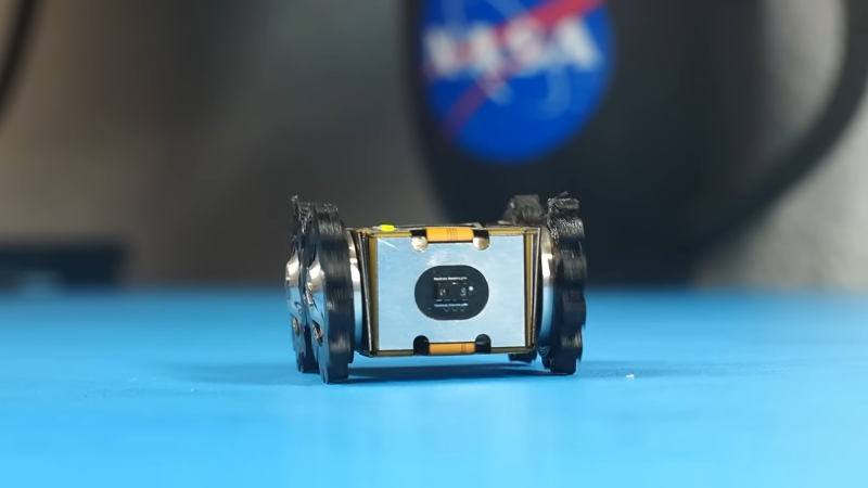
Yes, [Carl] decided to build a tiny robotic rover out of a foldable PCB. This choice was made as using a flexible foldable PCB would allow for the creation of a 3D chassis without the need for bulky connectors joining several boards together. A key part of the design was allowing the structure to unfold easily for serviceability’s sake. To that end, the structure is held together by the bolts that also act as the axles for the rover’s wheels. Even more brilliantly, the wheels are turned by motors built into the very PCB itself. Control is via a PlayStation controller, connected wirelessly to command the robot.
The little bot is surprisingly capable, especially when juiced up with a twin-cell lithium battery. It’s tiny, with minimal ground clearance, so it’s not the best at driving on rough surfaces. Having all-wheel-drive helps, though.
[Carl] specifically credits Altium Designer for making the design possible, thanks to its advanced 3D visualization tools that support foldable PCBs. Video after the break.


I thought it looked familiar but then again I tend to lose track of things…
Yeah, sorry! That’s a dupe.
This site becomes more like Slashdot every day.
Well, this is almost a Tie. Both writers used 4 paragraphs to describe the item, but Dan used more words. Please note that more words is not necessarily better. But I like the header image of Dan better, as it shows a closer view of the item being discussed. so for that choice alone I delcare him the winner today.
and now on topic:
It is interesting to use reinforced flexible pcb’s as constructional elements, but I am hesitant to implement it, as this makes it very difficult to repair. but it saves space by eliminating connectors and cables between parts. that’s for sure.
It’s too bad Altium Designer is priced out of reach for your average hacker/maker.
Apparently not if you’re willing to do advertising for them on YouTube!
Snark aside, everyone’s trying to integrate PCB design into physical CAD design stuff these days. I can’t imagine this would be impossible with other tools.
And really, you could do this with free software too. Design the frame with the nice metal-bending workspace in FreeCAD, export the outlines to your PCB layout. (What am I even saying? The PCBs are all square here anyway.)
Point being: this is a cool hack, but it’s not at all dependent on the tools he chose to / got sponsored to use.
One advice i always give to students is that if you think your pcb is done, just print the layout on a piece of paper and cut it out. Just to check the mechanics.
That might be a suitable “low tech” option, but having the propper tool is usually beneficial.
I do this all the time! super useful to double check footprints.
Sorry Lewin, Dan beat you to this one already. https://hackaday.com/2023/03/25/single-flex-pcb-folds-into-a-four-wheel-rover-complete-with-motors/
As usual HAD writers never read a single article from HAD.
duplicate…
was kinda disappointed as I expected the PCB to actually fold automatically using nitinol or something.
Maybe next version :D