Designing a circuit is a lot easier on paper, where components have well-defined values, or lacking that, at least well-defined tolerances. Unfortunately, even keeping percentage tolerances in mind isn’t always enough to make sure that circuits work correctly in the real world, as [Tahmid] demonstrates by diagnosing a buck converter with an oddly strong voltage ripple in the output.
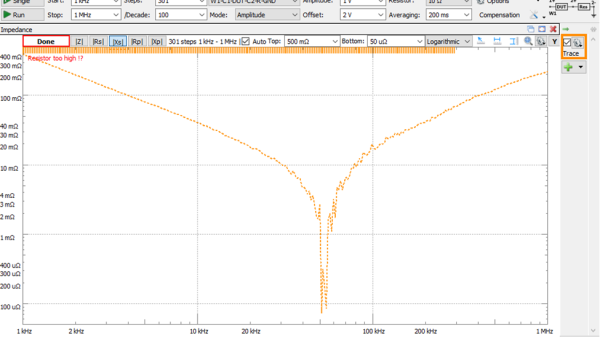
Some voltage ripple is an inherent feature of the buck converter design, but it’s inversely proportional to output capacitance, so most designs include a few smoothing capacitors on the output side. However, at 10 V and a 50% duty cycle, [Tahmit]’s converter had a ripple of 0.75 V, significantly above the predicted variation of 0.45 V. The discrepancy was even greater at 20 V.
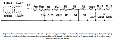
The culprit was the effect of higher voltages on the ceramic smoothing capacitors: as the voltage increases, the dielectric barrier in the capacitors becomes less permittive, reducing their capacitance. Fortunately, unlike in the case of electrolytic capacitors, the degradation of ceramic capacitors performance with increasing voltage is usually described in specification sheets, and doesn’t have to be manually measured. After finding the reduced capacitance of his capacitors at 10 V, [Tahmid] calculated a new voltage ripple that was only 14.5% off from the true value.
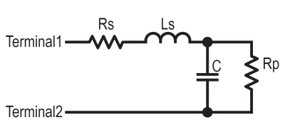
Anyone who’s had much experience with electronics will have already learned that passive components – particularly capacitors – aren’t as simple as the diagrams make them seem. On the bright side, they are constantly improving.
analog discovery2 Articles
Why Is My 470uF Electrolytic Cap More Like 20uF?
Inductors are more like a resistor in series with an ideal inductor, resistors can be inductors as well, and well, capacitors aren’t just simply a capacitance in a package. Little with electronics is as plain and simple in reality as basic theory would have you believe. [Tahmid Mahbub] was measuring an electrolytic capacitor with an LCR and noticed it measuring 19 uF despite the device being rated at 470 uF. This was because such parts are usually specified at low frequencies, and at a mere 100 kHz, it was measuring way out of the specification they were expecting. [Tahmid] goes into a fair bit of detail regarding how to model the equivalent circuit of a typical electrolytic capacitor and how to determine with a bit more accuracy what to expect.
The basic equivalent circuit for a capacitor has a series resistance and inductance, which covers the connecting leads and any internal tabs on the plates. A large-valued parallel resistor models the leakage through the dielectric in series with the ideal capacitance, which is responsible for the capacitor’s self-discharge property. However, this model is still too simple for some use cases. A more interesting model, shown to the left, comprises a ladder of distributed capacitances and associated resistances that result in a progressively longer time-constant component as you move from C1 to C5. This resembles more closely the linear structure of the capacitor, with its rolled-up construction. This model is hard to use in any practical sense due to the need to determine values for the components from a physical part. Still, it is useful to understand why such capacitors perform far worse than you would expect from just a simple equivalent model that looks at the connecting leads and little else.
Continue reading “Why Is My 470uF Electrolytic Cap More Like 20uF?”